
Total Build Time: 996 Hours
Today I rigged my rudders (prior to installing my glareshield/fuel tank which would restrict access to the pedals), and have a few closeup shots of some details.
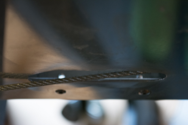
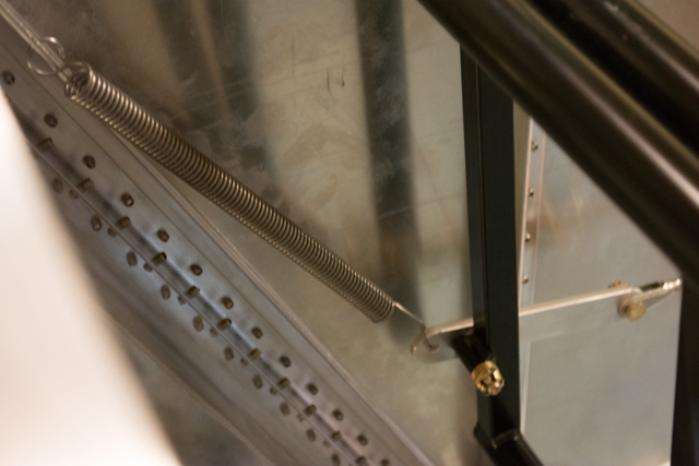
The first step of the Waiex rigging process links the rudder to the mixer in the middle of the aft fuselage. The cables run through slots previously created in the aft fuselage sides.
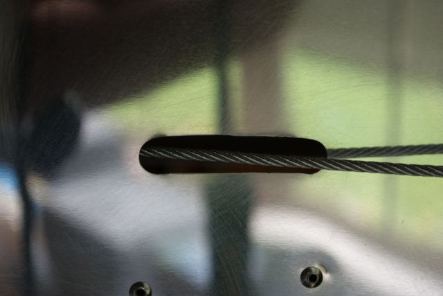
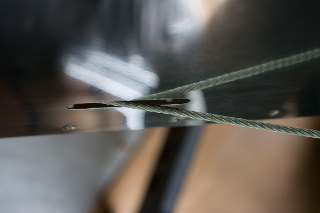
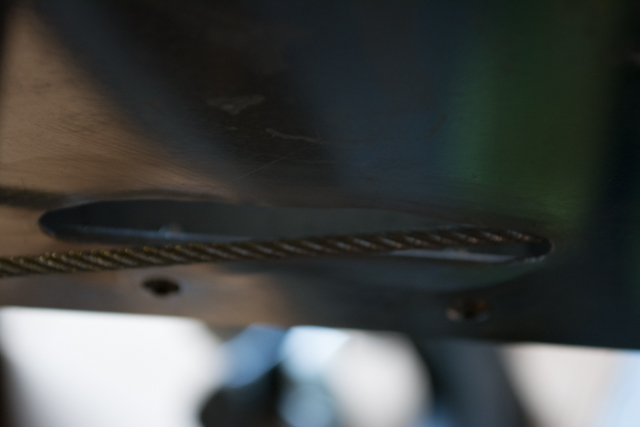
The 2 pictures above are of the cable on the LEFT side of the fuselage. I found no issues with the way the cables run on the LEFT side, with plenty of clearance from the fusalge skin through full travel of the rudder.
However the slots cut in the RIGHT side, per the plans, are the same size as the LEFT side, however I found they were entirely too small. The reason is the way the rudder drive horn is shaped… the RIGHT side of the drive horn imparts much more lateral movement to the cable.
I had to make the RIGHT side slot almost twice as long (after trial and error) to accommodate the cable. Reference the rivets in the above photos versus the rivets in the photos below. The sequence of photos below cover the full range of rudder travel.
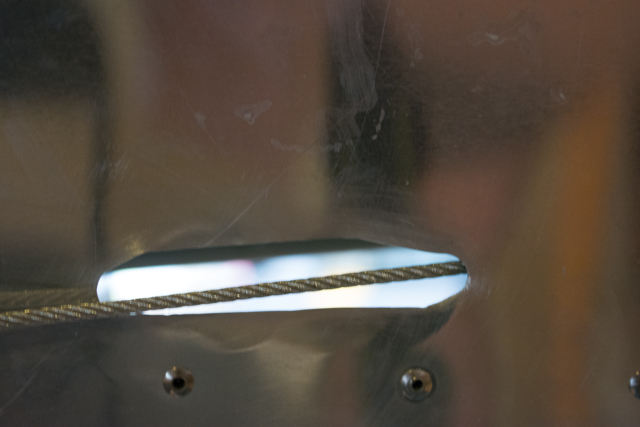
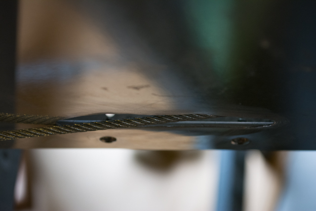
You can see in the last 2 shots above that even after enlarging the slot in the skin, the cable comes quite close to both the fore and aft edge of my newly enlarged slot, which is almost double in length of what the plans call for. This is simply because the RIGHT side rudder arm has a longer arm, thus a larger swing radius than the LEFT side. This is no big deal, and will ultimately be covered (visually and aerodynamically) by a small fairing. It may be OK per the plans that the cable rubs on the skin, but I didn’t like it so I made the slots bigger.
Per the rigging process, I then positioned the rudder cables to the rudder pedals. I marked the aluminum rudder pedal attachments (the name of the part escapes me) and pulled the cables tight to mark the bolt holes.
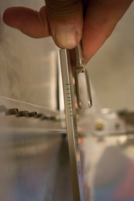
After rigging the cables to the appropriate lengths, I found that the rudder return springs as called for in the plans were cut entirely too long, with very little tension (and entirely too much slack when pedals pressed forward to the rudder stop). I cut the springs approximately 2 inches shorter (the plans do call to trim the springs to center the rudder).
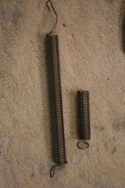
The springs at this new shorter length keep a good tension in the rudder cables even if the rudder is moved without pedal input (either aerodynamically or from forces on the ground.) If I have cut them too short and the springs start to lose tension, they are easy enough to replace (they are screen door springs.)