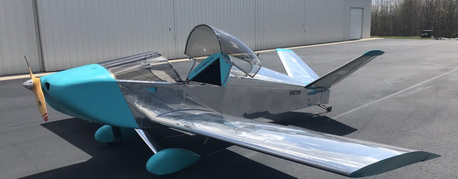
Total Build Time: 1002 Hours.
Continuing from my previous post on electrical wiring, this post covers my work on firewall penetration/protection, battery current sensor and intercom wiring. I’m still not quite finished with wiring but will follow up later.
Firewall penetration for my electical wires passed through a large hole covered by a firewall penetration kit from Aircraft Spruce, consisting of a stainless steel fitting riveted to the firewall and silicon fire sleeve sealed with a silicon paste and hose clamps.
Link to the kit here
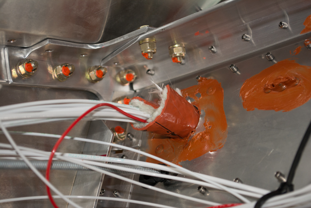
I continued to tidy up the wires behind the firewall in preparation for the fuel tank installation.
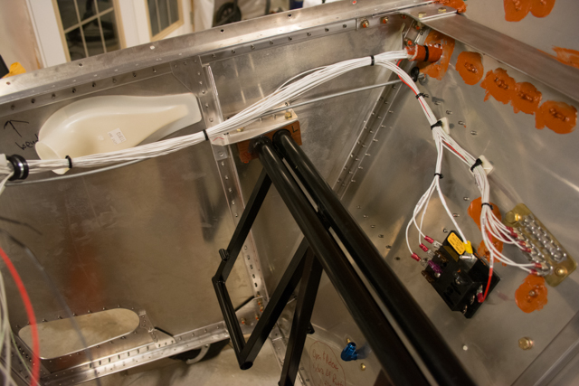
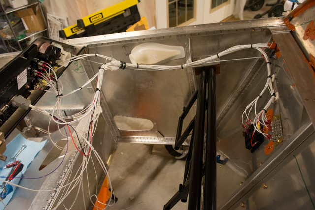
The hornets nest of wires on the left side of the above picture will be corralled once the fuel tank is installed, I’ve pre-located some clamps in the bottom of the glareshield to hold them.
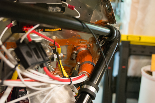
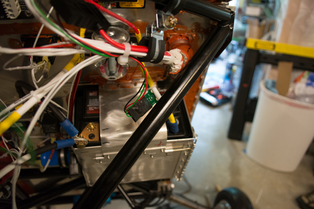
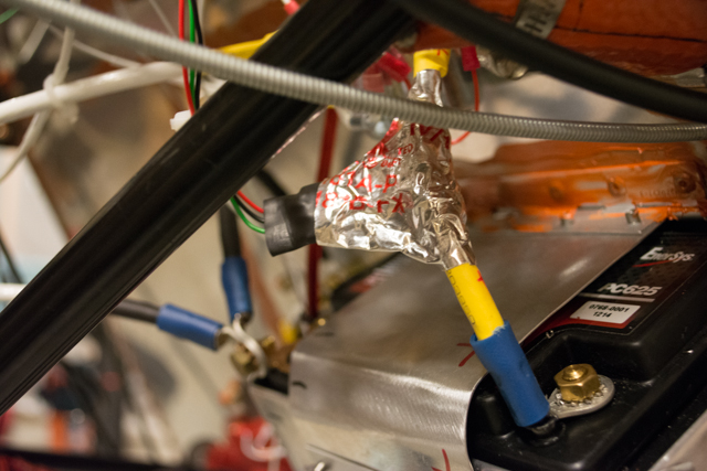
Next, I installed an MGL magnetic current sensor to the main positive lead from the battery. This will allow me to read current to/from the battery on my MGL iEfis screen in the cockpit. I will be able to see the battery charging/discharging during flight, giving me insight on the functioning of the alternator, while helping me determine if my plugged-in devices are drawing too much power (ipad, gps, etc.)
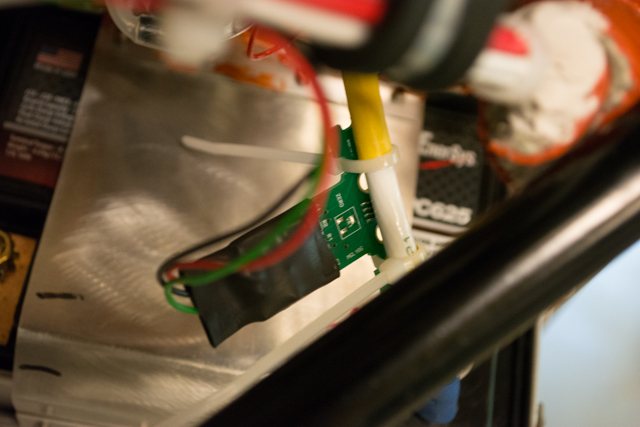
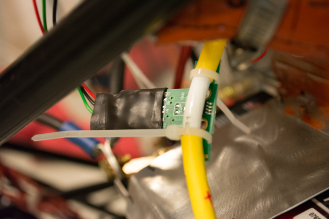
To protect this circuit board, I first wrapped it in electrical tape, then wrapped it in aluminum HVAC tape to help stave off magnetic interference. I’m no electrical engineer, but my hope is the aluminum wrapping around the sensor will help insulate it from magnetic interference, along with heat reflection.
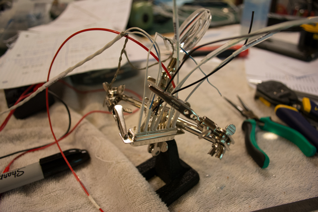
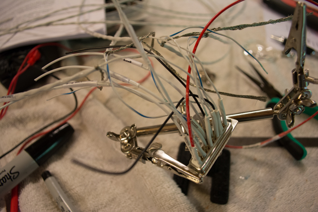
Next comes the intercom/radio harness. MGL does sell a harness (at a premium price), however the location of my intercom plugs (on the turtledeck #1 former) means I need long lead wires to the plugs. This also would be accommodated by MGL, but at additional cost. Also, I didn’t want to drill holes large enough to fit the pre-wired intercom plugs, versus holes just large enough to fit the wires. Therefore I decided to build the harness myself. I used 2-conductor shielded wire for each plug.
Here are some great videos on dealing with shielded intercom wire and soldering harnesses:
Stripping shielded audio cable
This proved to be a time-consuming task… but so is building an airplane!
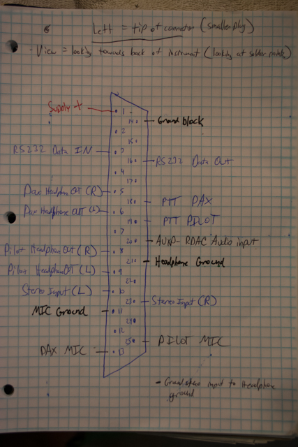
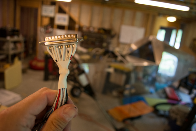
Below are pictures of my harness wiring diagram, and pics of me wiring the DB25 connector for the MGL V6 Radio. Note in the diagram below, which I corrected later… Left = tip of connector is true for the Headset, however the MIC plug is the smaller of the 2, the Headset plug is the larger of the 2.
Below is a progression of soldering the harness.
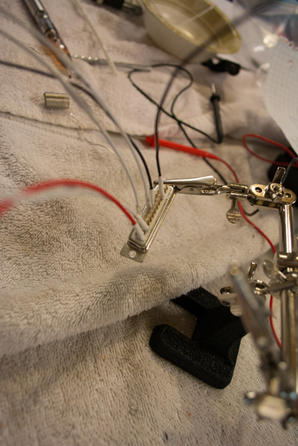
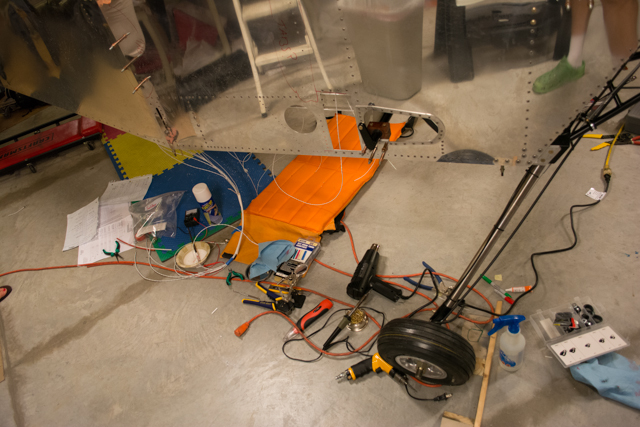
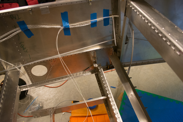
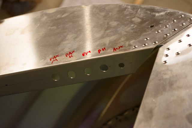
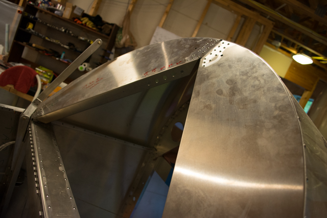
With the radio-end of the harness complete, I ran the wires along the fuselage and prepared my intercom holes in the turtledeck #1 former. Included in the first pic below are the 2 wires that will go to the push-to-talk (PTT) switches on the top of my control sticks (the 2 wires exiting the bottom of the photograph.) I wired my headphone plugs as MONO (left side only) since my headsets are mono. For the music (AUX) input, it will be wired stereo but I’ll use a 3.5mm stereo-to-mono adapter when I plug music into it (resistors are required when going from stereo to mono, and they are inclusive to a stereo-to-mono adapter plug.) MGL did suggest that I wire everything stereo, but I chose not to since I know I will be using MONO headsets and didn’t want to complicate wiring further by installing resistors into the wiring harness.
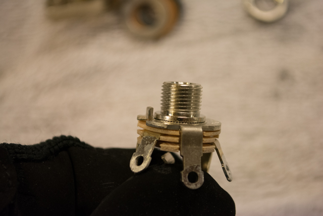
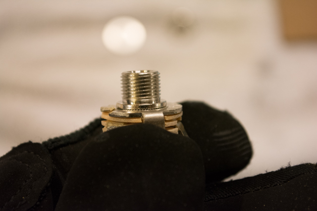
The headset plugs I ordered from Aircraft Spruce included a small tab that (I presume) are to prevent the plug rotating. However, the plugs need to be grounded through their wires and should not contact the grounded metal of the airframe. I didn’t know how to incorporate this tab into the installation, therefore in the following 2 pictures you’ll see the tab (on the left side of the threaded part), which I then removed with a dremel cutoff wheel.
Since my wires are planned and routed through a hole/grommet that would be too small to fit the headset plugs through, I’ll need to finish wiring the harness by soldering the wires to plugs on the floor behind the cockpit. This last picture is during that process and is as far as I’ve proceeded as of the writing of this post.