Total Build Time: 1303 Hours
This is a long post with lots of photos spanning about 3 months of intermittent work. Here is the order of operations in this post:
-Tail Fairing fabrication/installation
-Jacking up the aircraft
-Wheel pant fabrication/installation
-Landing Gear fairing fabrication
Quick note: I did fabricate but did not ultimately install the tail-wheel fairing. It was a very complicated part to make and I was not satisfied with the result I came up with, and also noted that many/most other Sonex/Waiex aircraft I have seen do not have this fairing installed, including some of the factory aircraft.
Tail Fairing Fabrication:
The first part that I decided to fabricate is the fairing that goes between the stabilators on the top/aft portion of the aft fuselage. I should preface this by saying that I have never done any sort of metalwork involving the annealing and forming of metal parts (making curved bends), except for the specific bend angles I’ve had to make in parts thus far in the build. I’ve never “formed” metal, only made straight-line bends in metal.
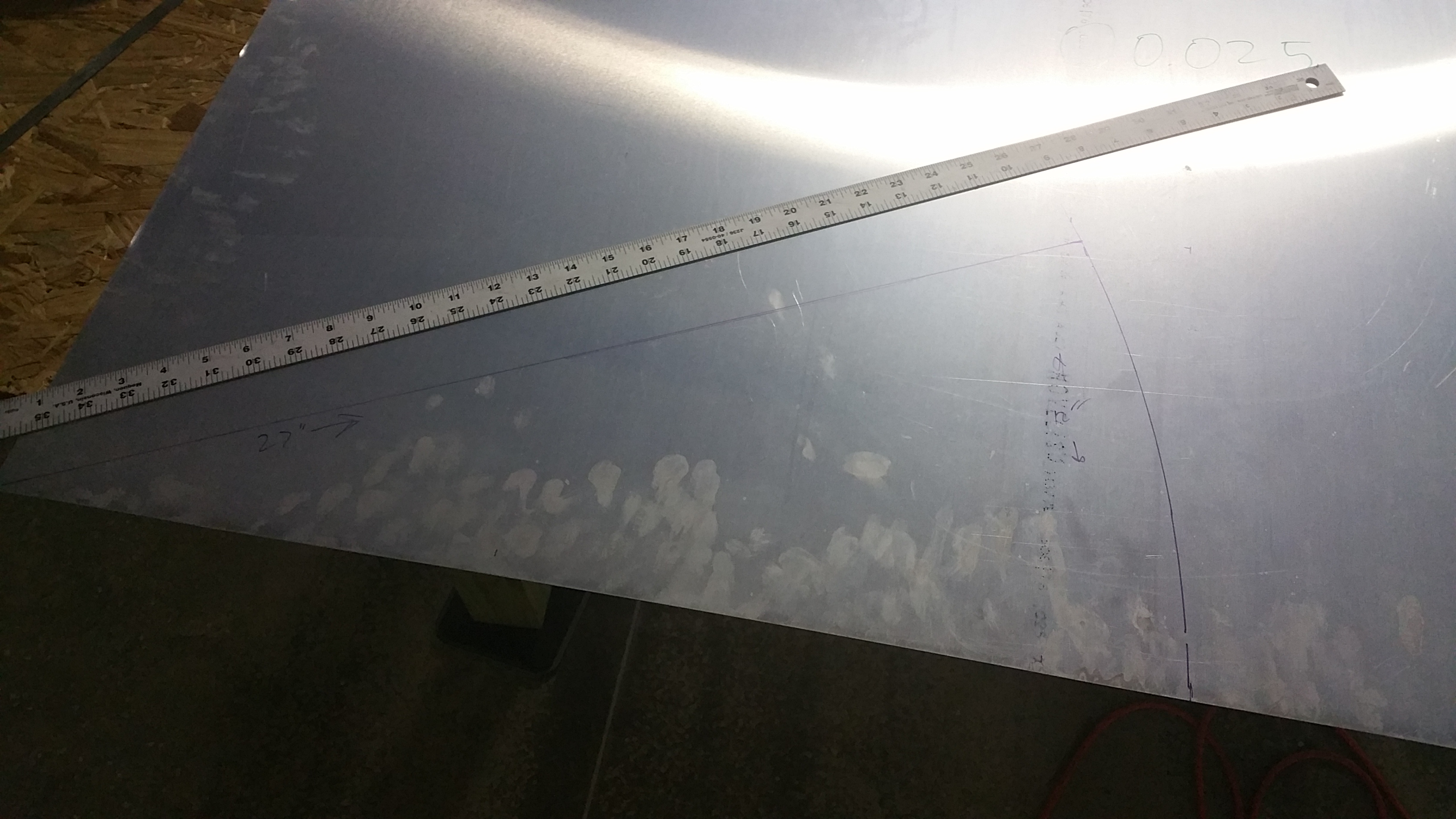
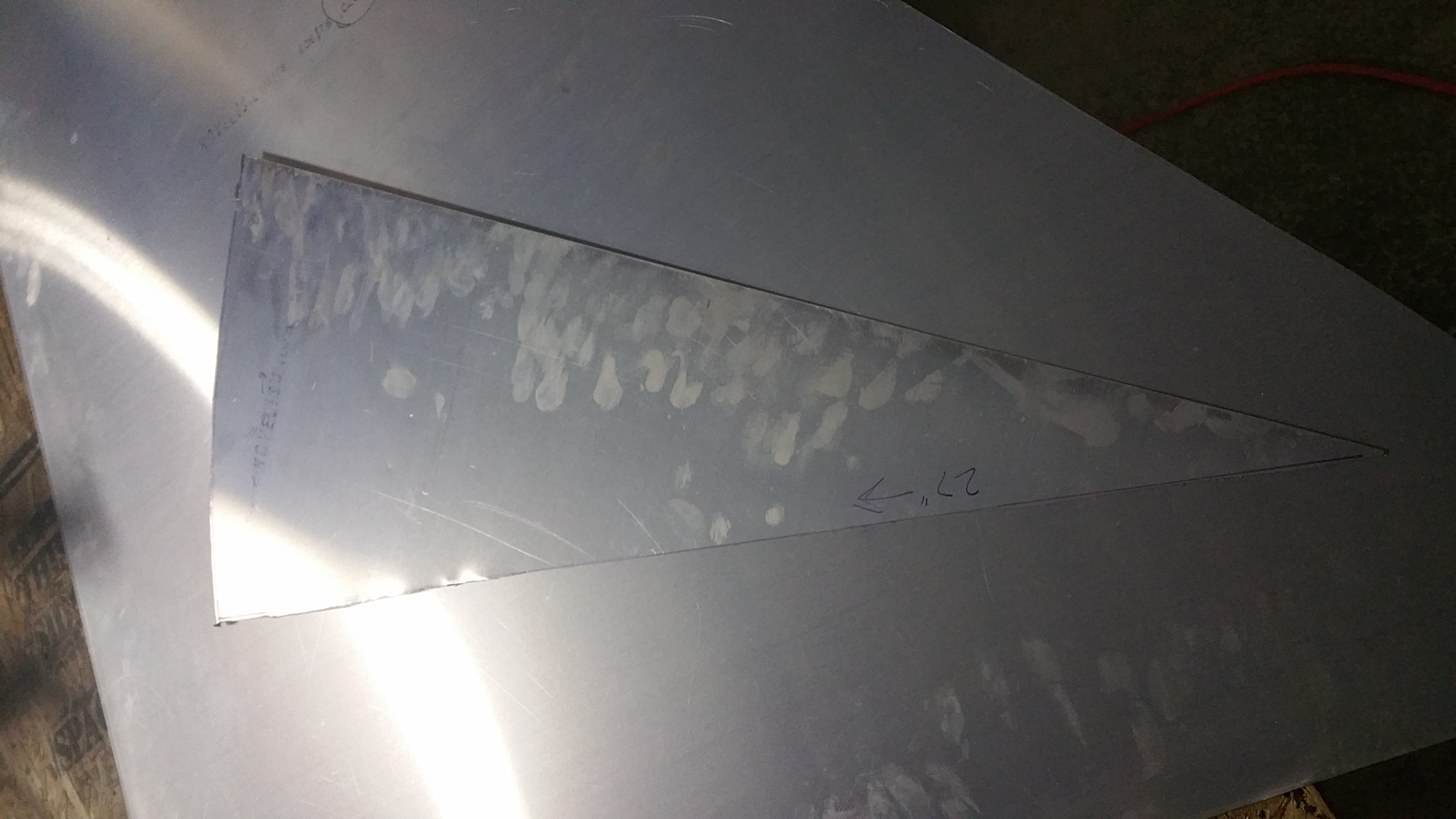
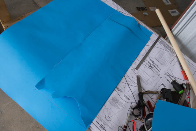
I started by measuring and cutting the part using the plans measurements:
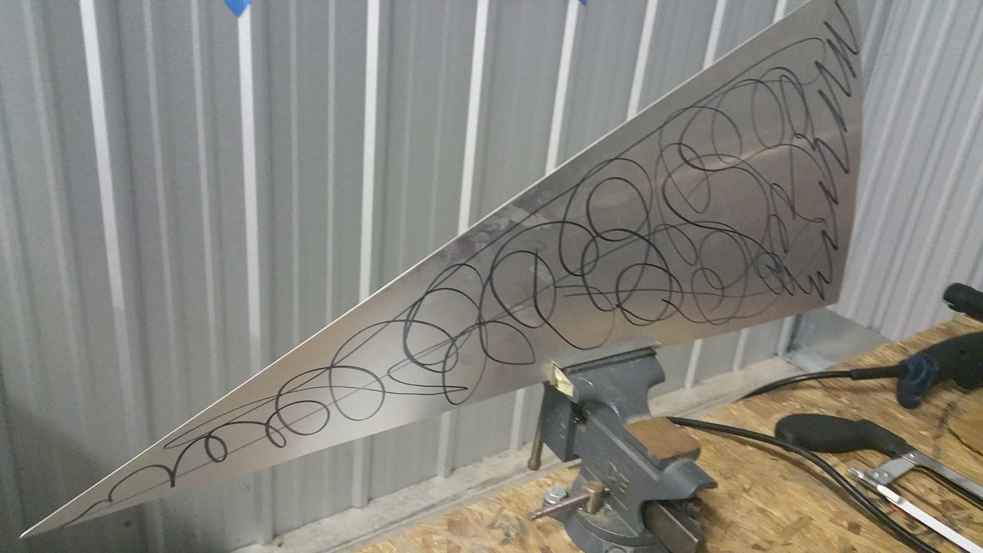
I then used what is often referred to as the “sharpie” method of annealing the aluminum. The purpose of this is to “soften” the metal and make it easier to form into a new shape. Doing so will drastically reduce the structural strength of the part which is why I’ve not done this to any part in the past. However this is a cosmetic/aerodynamic part, and is not used to hold any other parts together in a structural manner.
This “sharpie” method is based on the fact that (in my uneducated layman’s understanding of this method) the annealing temperature point of the aluminum alloy used in this aircraft (6061-T6) happens to coincide with the temperature that a sharpie mark will disappear. Thus, you mark the part, heat it from the opposite side, and when the sharpie marks disappear you know you have reached annealing temperature and the part will be much easier to form.
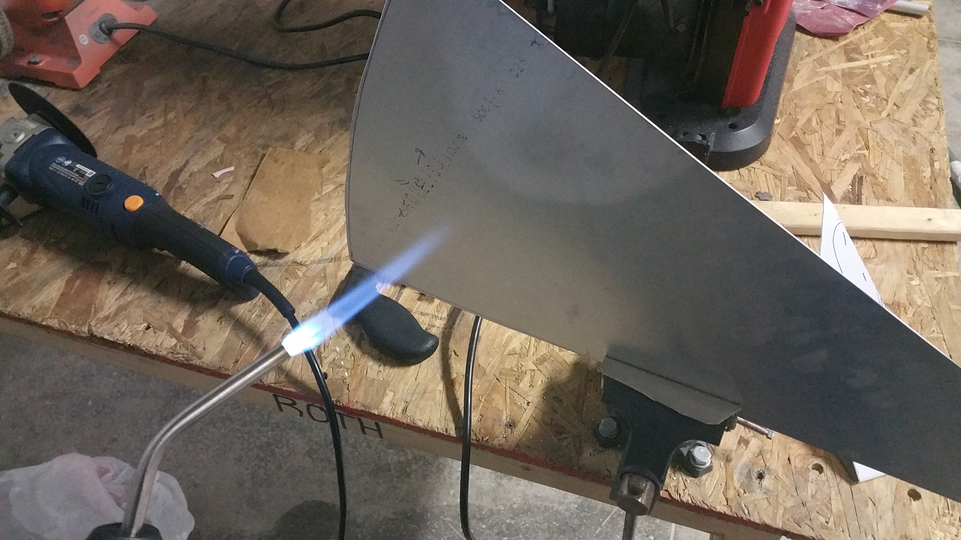
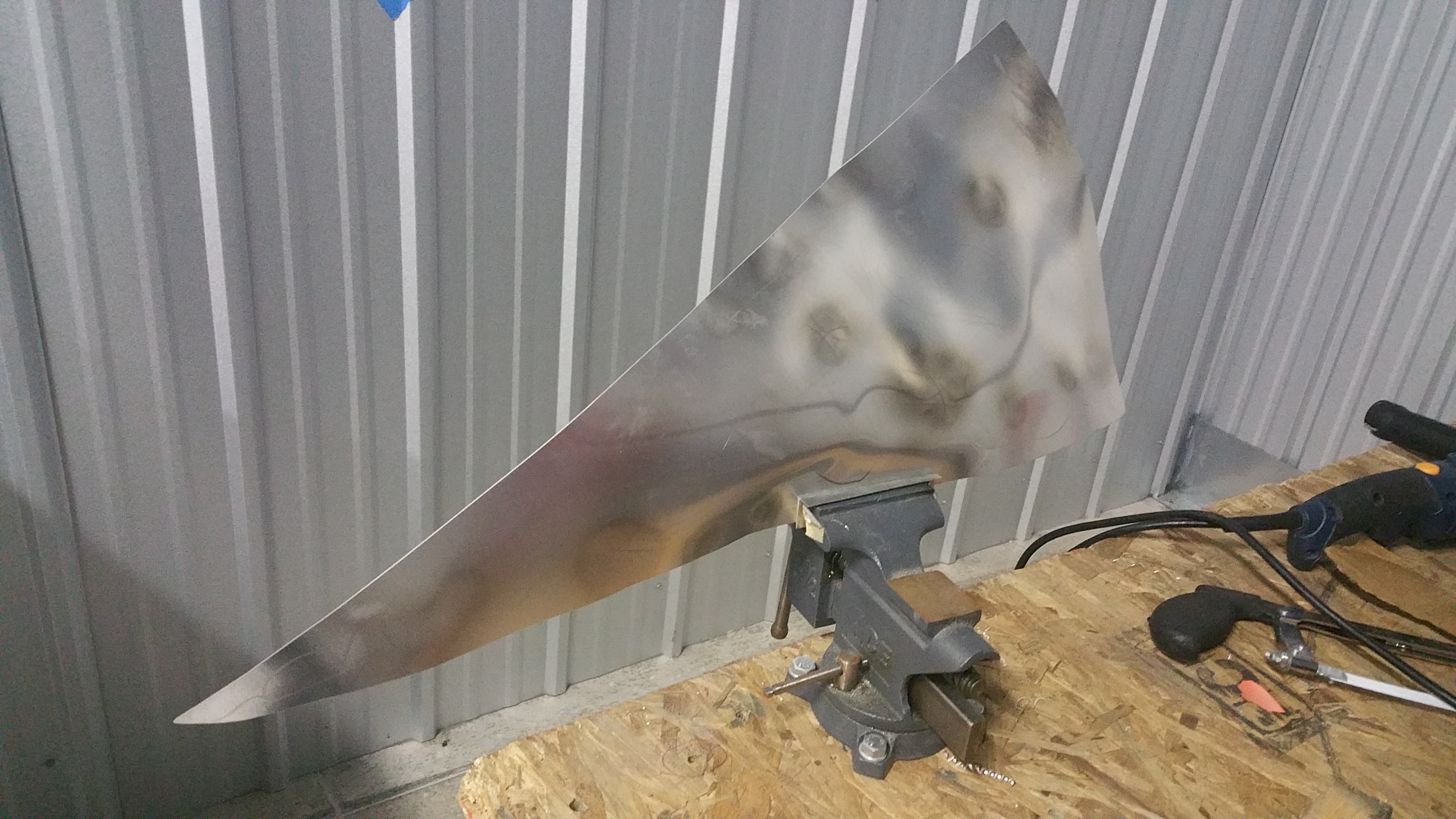
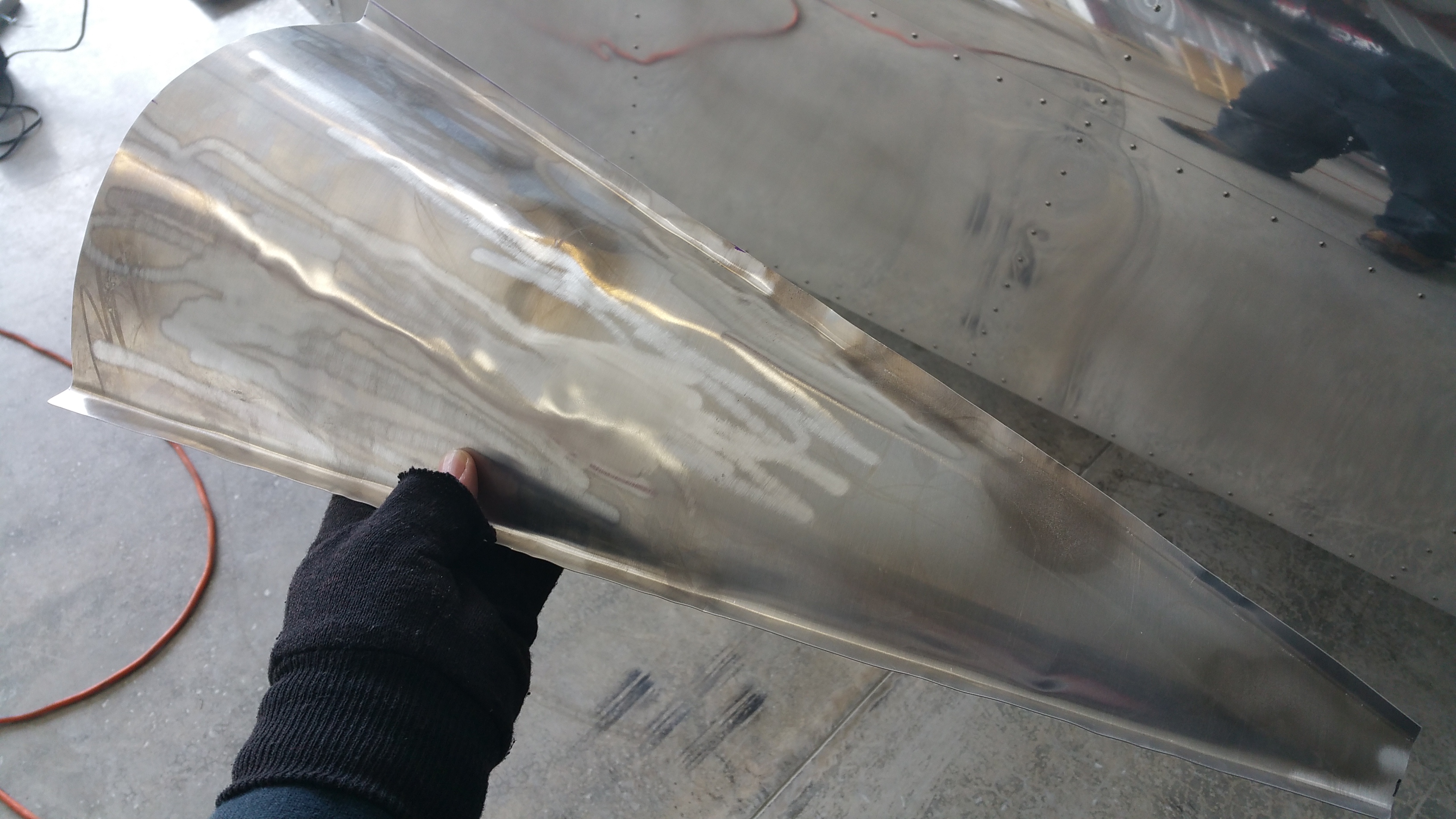
I then formed this part, mostly using my hands and a wooden dowel, to the shape needed to fill in the gap between the stabilators.
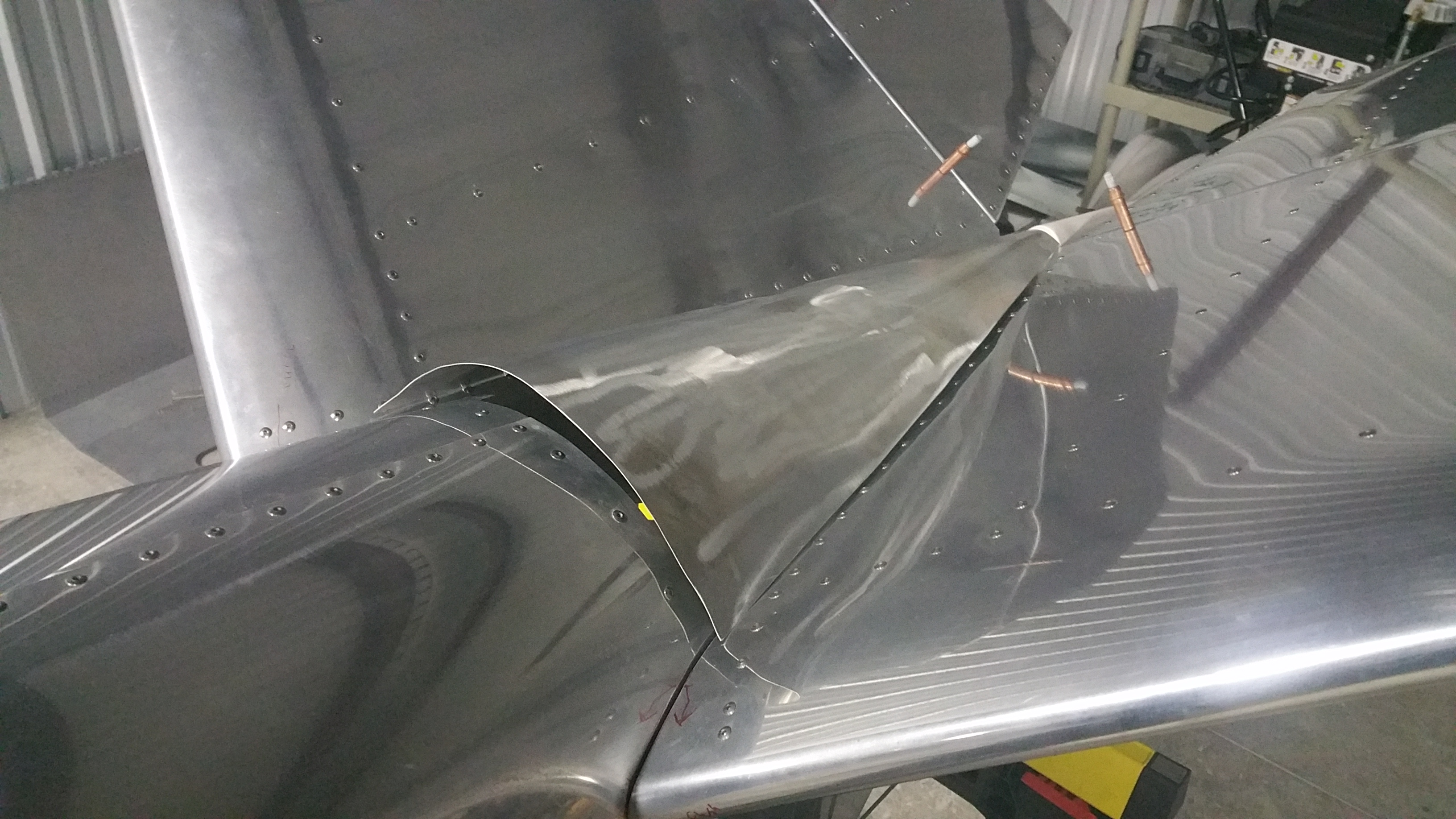

It’s not the prettiest part I’ve made on my plane (in fact I believe it to be the ugliest) but I am satisfied it will get me to the end of the project. I am likely to re-make the part in the future, and since it’s an easily removable part it will be easy to replace.
After several iterations/trims and re-bending of the flange, I was finally satisfied with the fitment of the fairing.
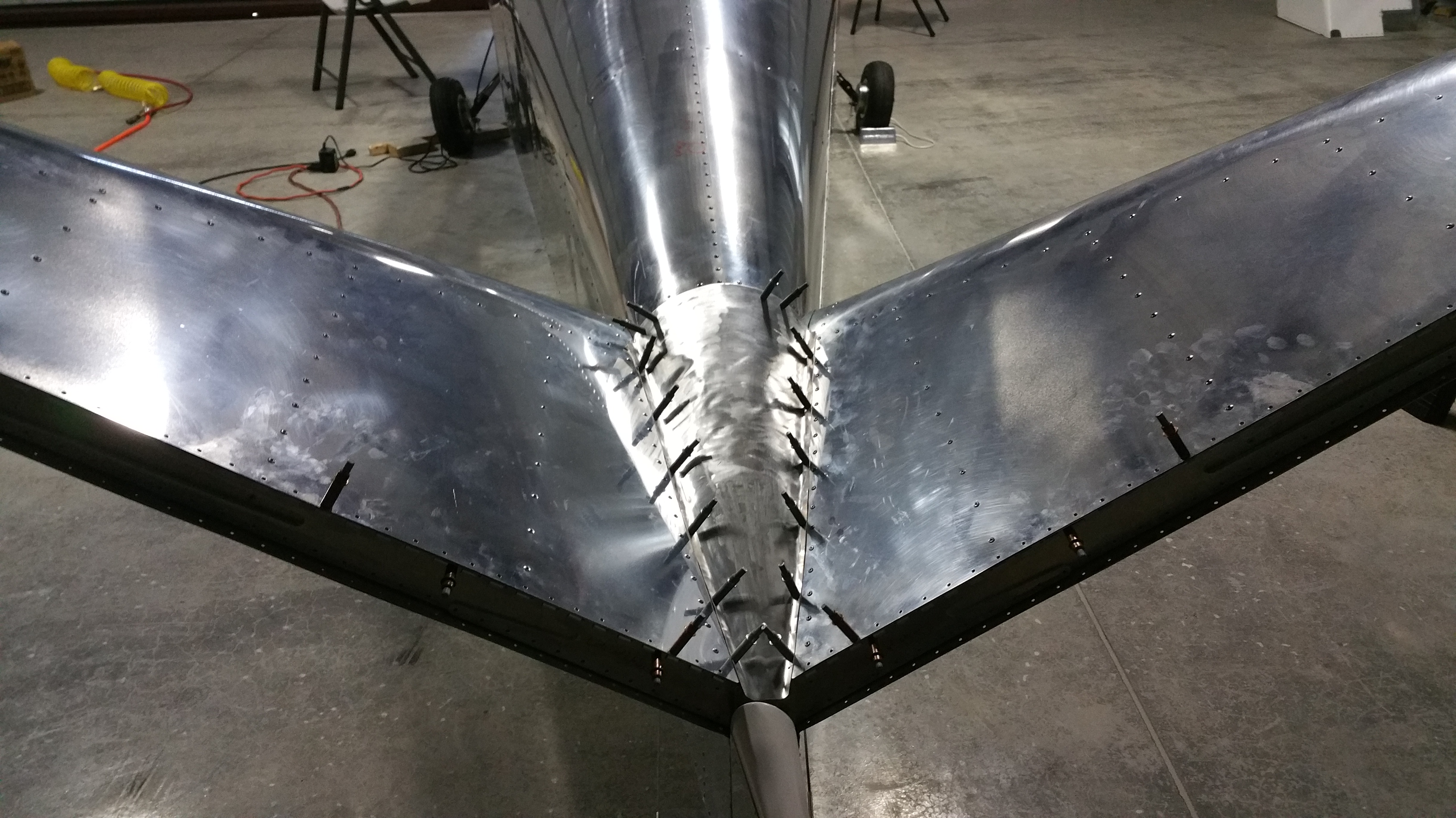

Tail Fairing Installation:
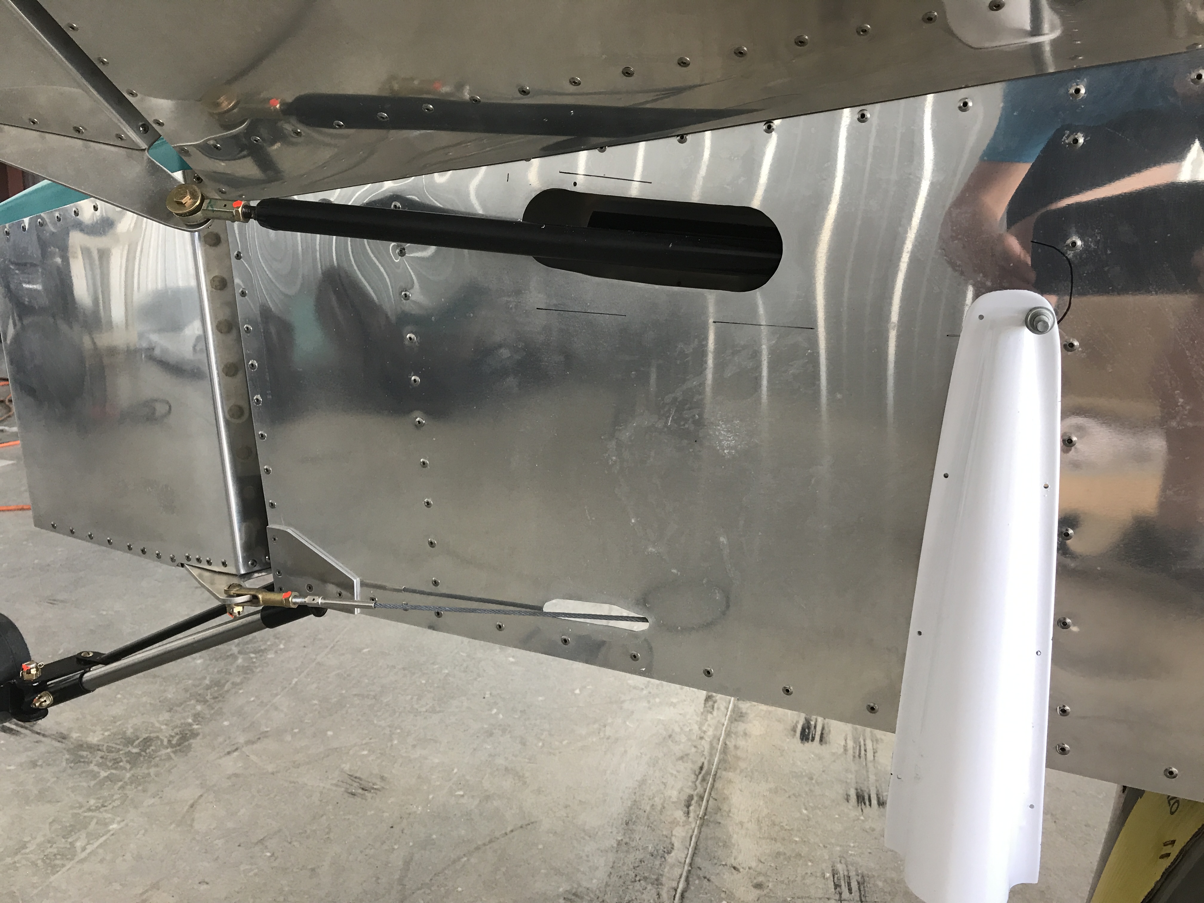
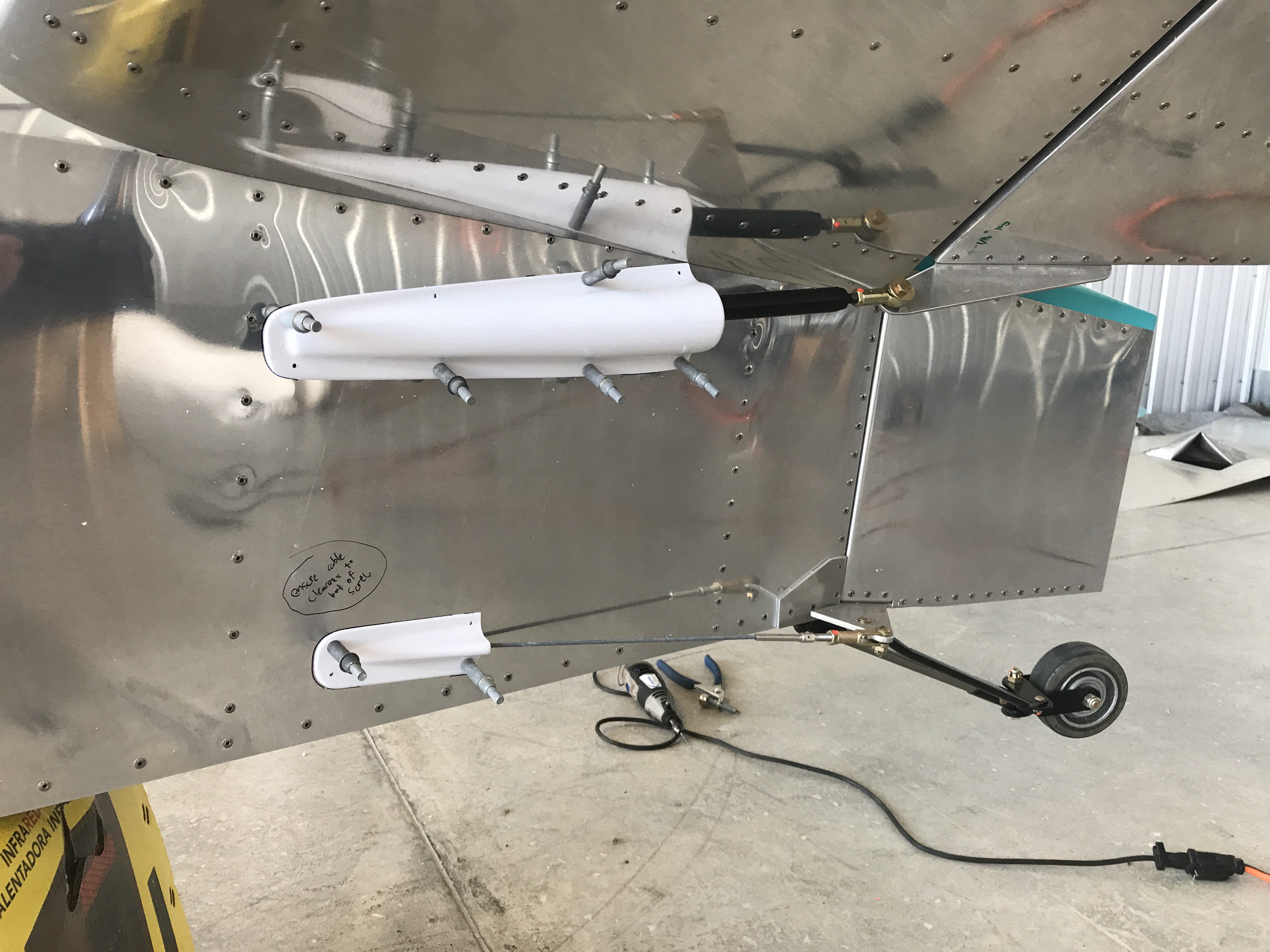
There are 4 additional fairings added to the tail section that cover the control connections to the ruddervators and rudder. I opted to purchase the pre-fabricated plastic fairings offered by Sonex rather than fabricate my own aluminum fairings. This was largely due to the experience I had with the above fairing.
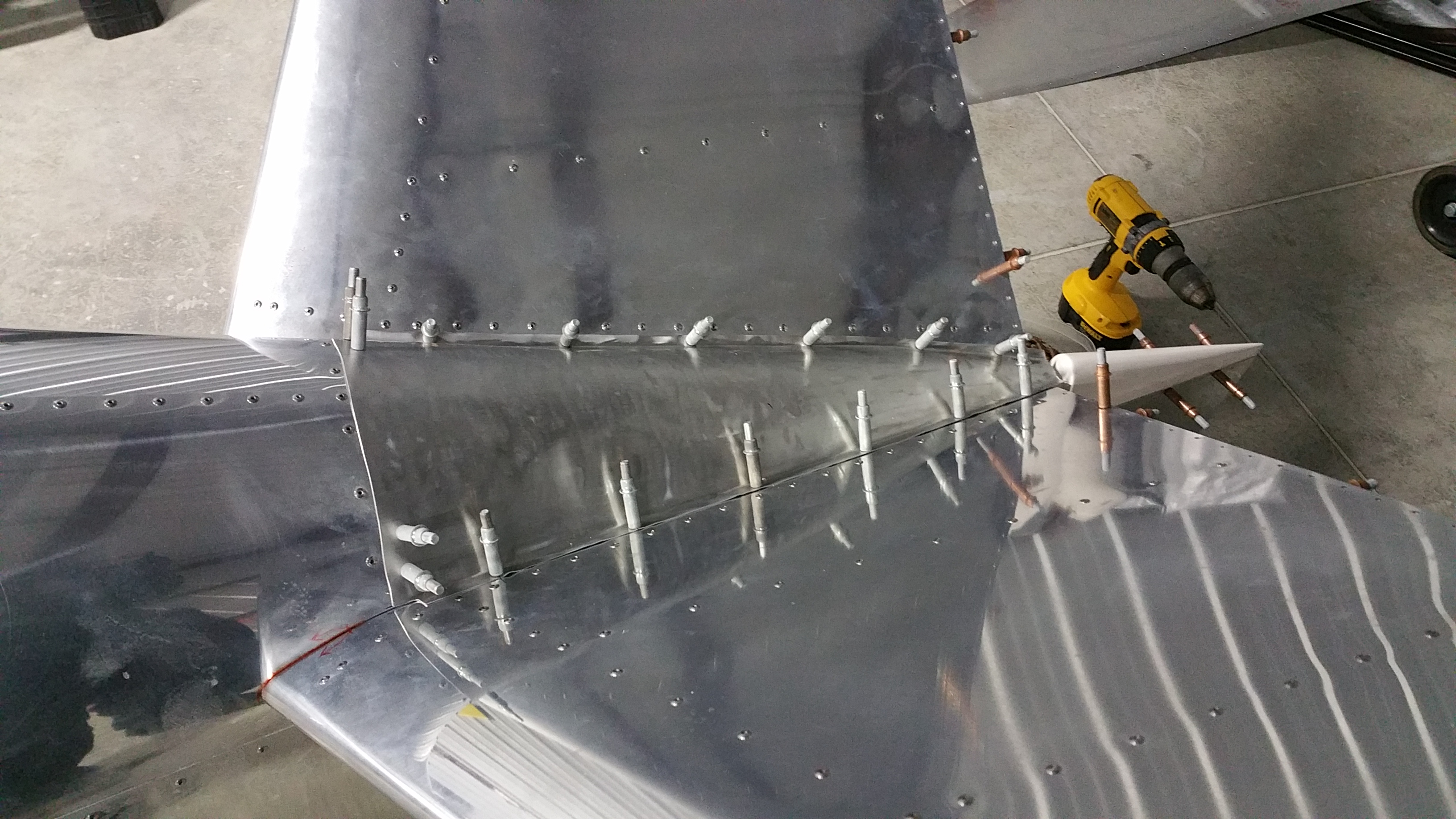
Below is marking the fairings for installtion, paying careful attention to where the fasteners protruded into the fuselage. I didn’t want to have any sort of interference with the control connections.
Left side fairings clecoed in place.
Jacking up the aircraft:
In order to fabricate and install the wheel pants, I would need to remove the wheels to make modifications to the brake assembly, which is used to attach the wheel pants. I would also use this opportunity to re-pack the main wheel bearings, a standard maintenance item.
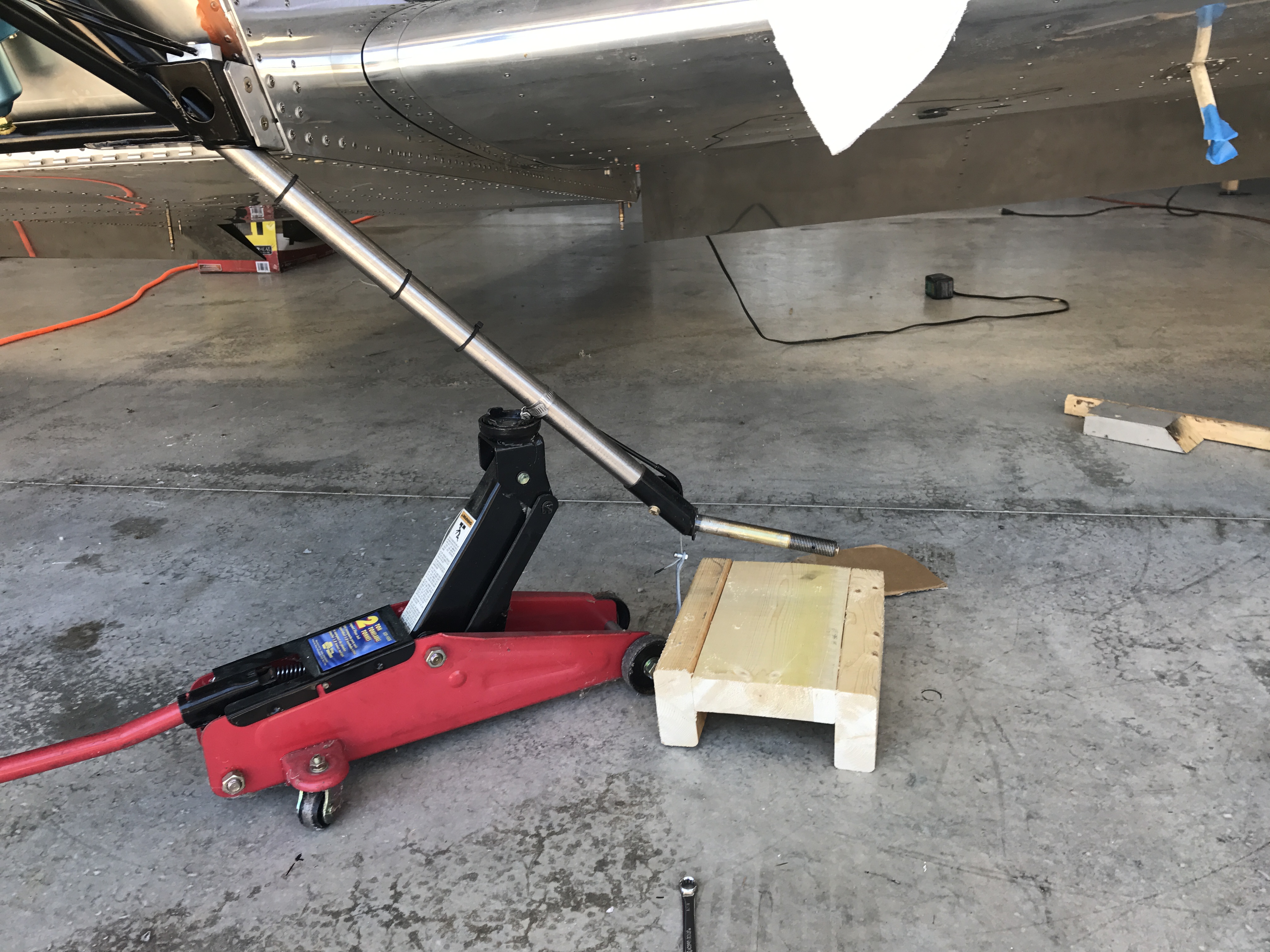
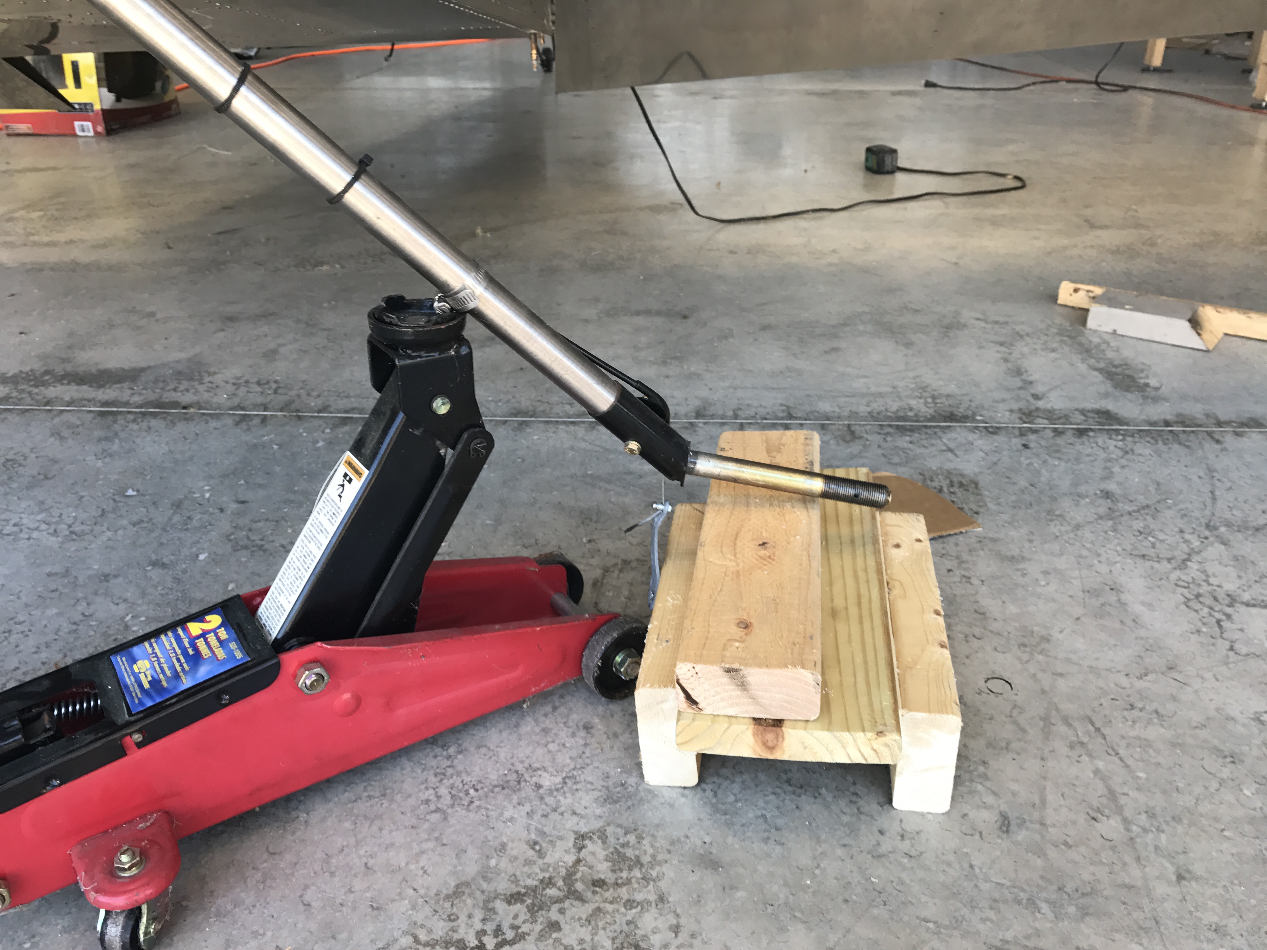
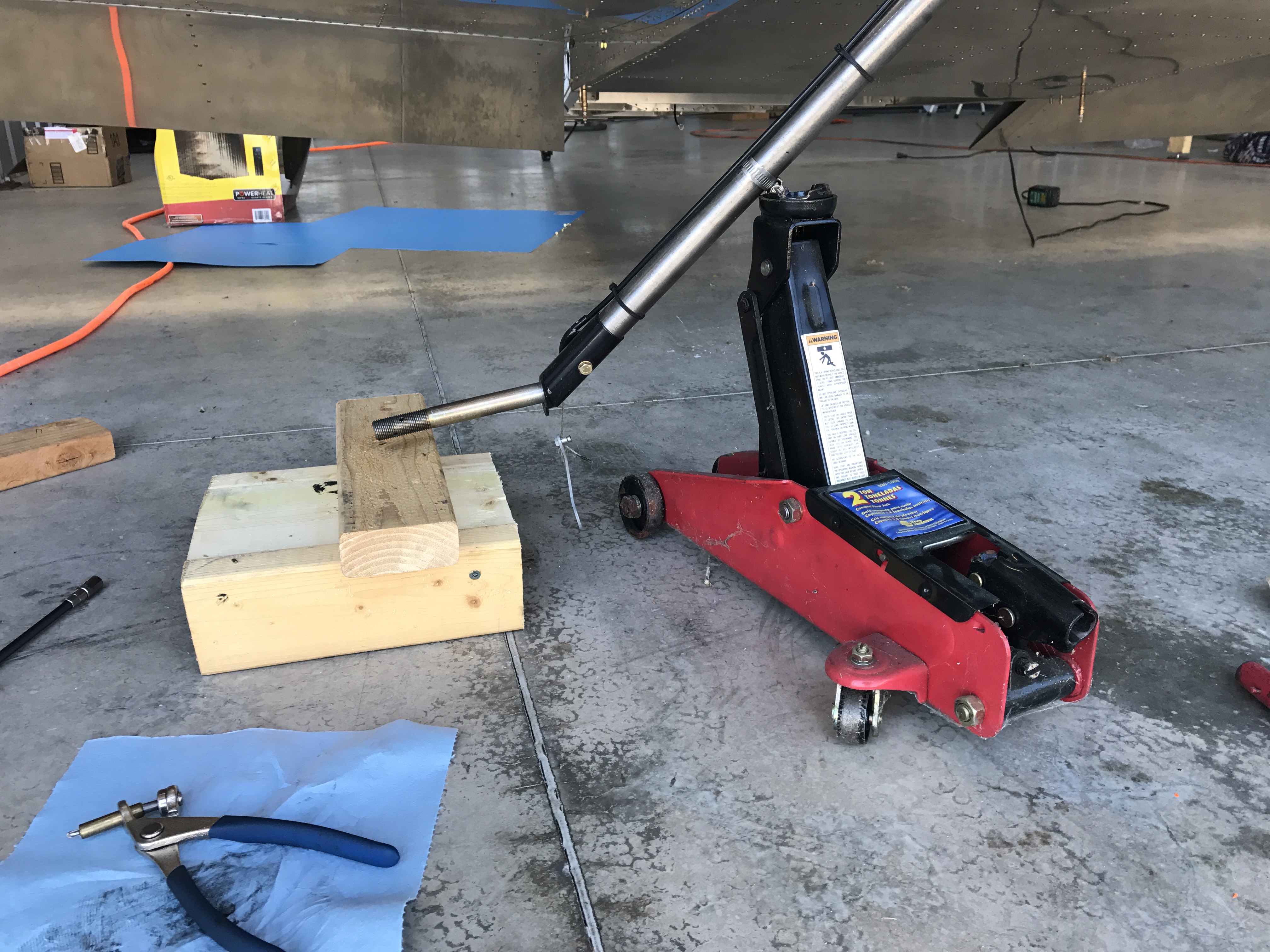
There is no jacking-up point built-in to the Sonex/Waiex airframe, so I would have to come up with something. Here is a method that I tried that seemed promising at first, but ultimately I was not happy with. It simply seemed way too unstable due to the height between the jack and the support, as well as the angle between the support and the bottom of the fuselage.
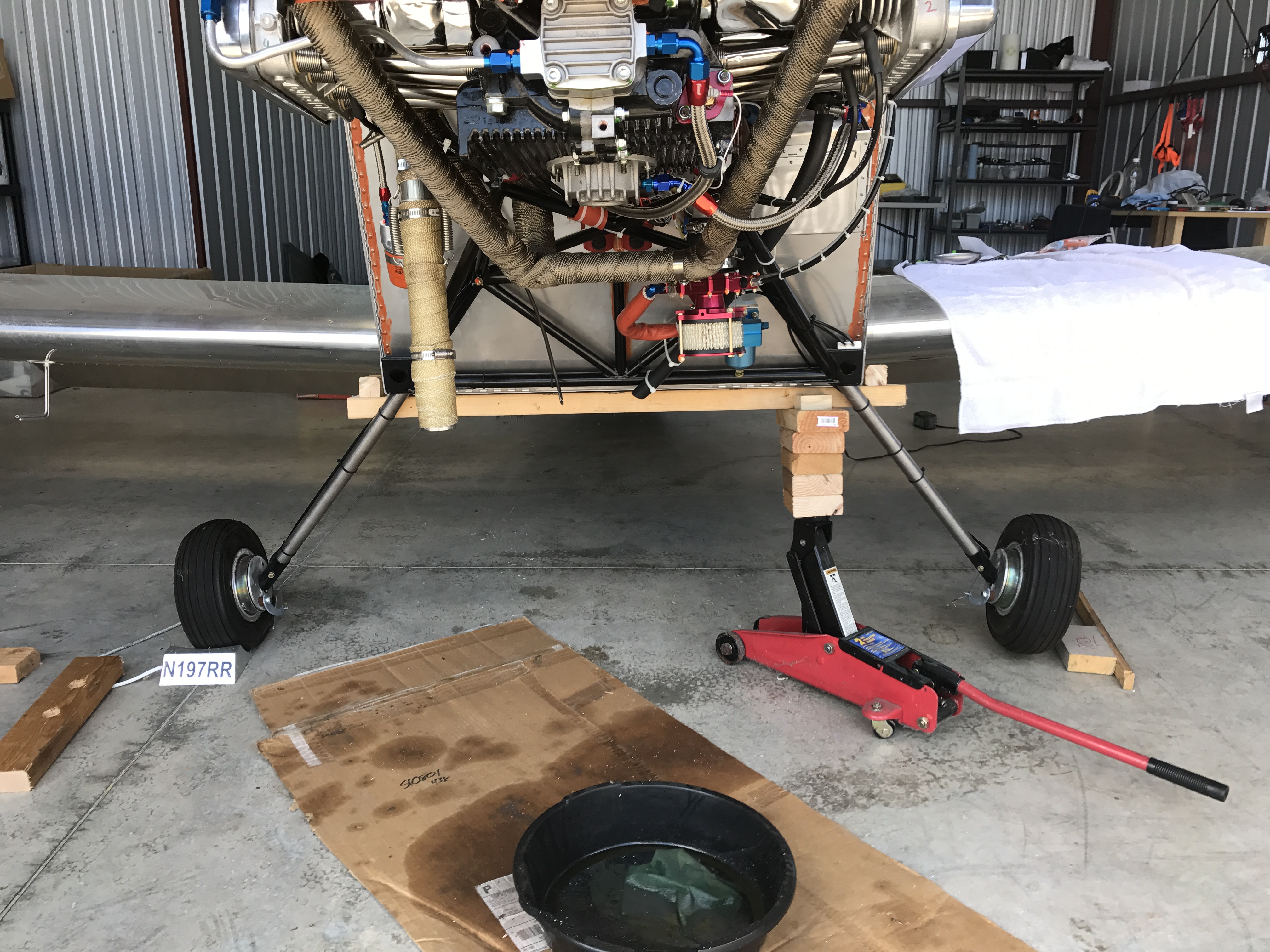
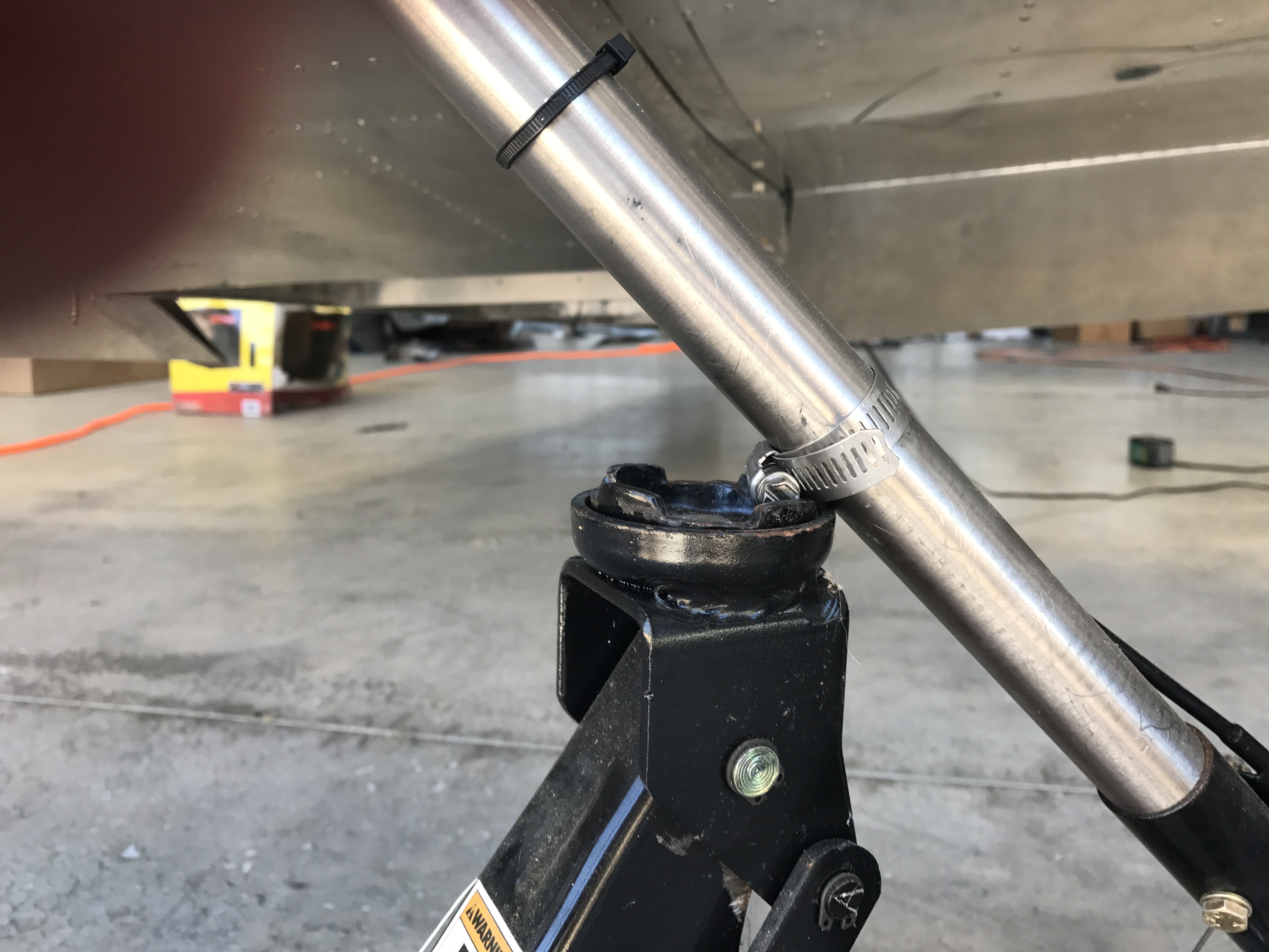
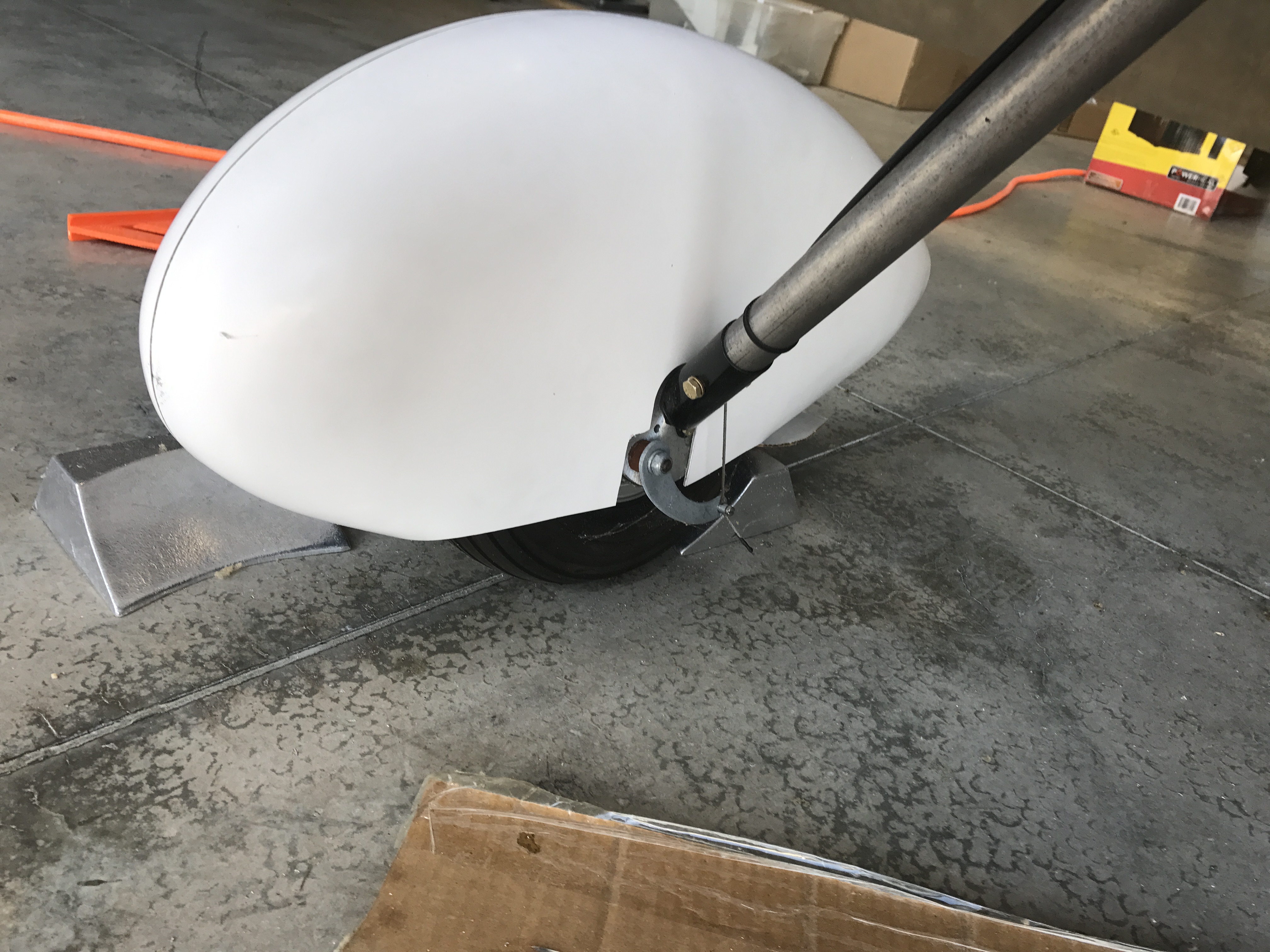
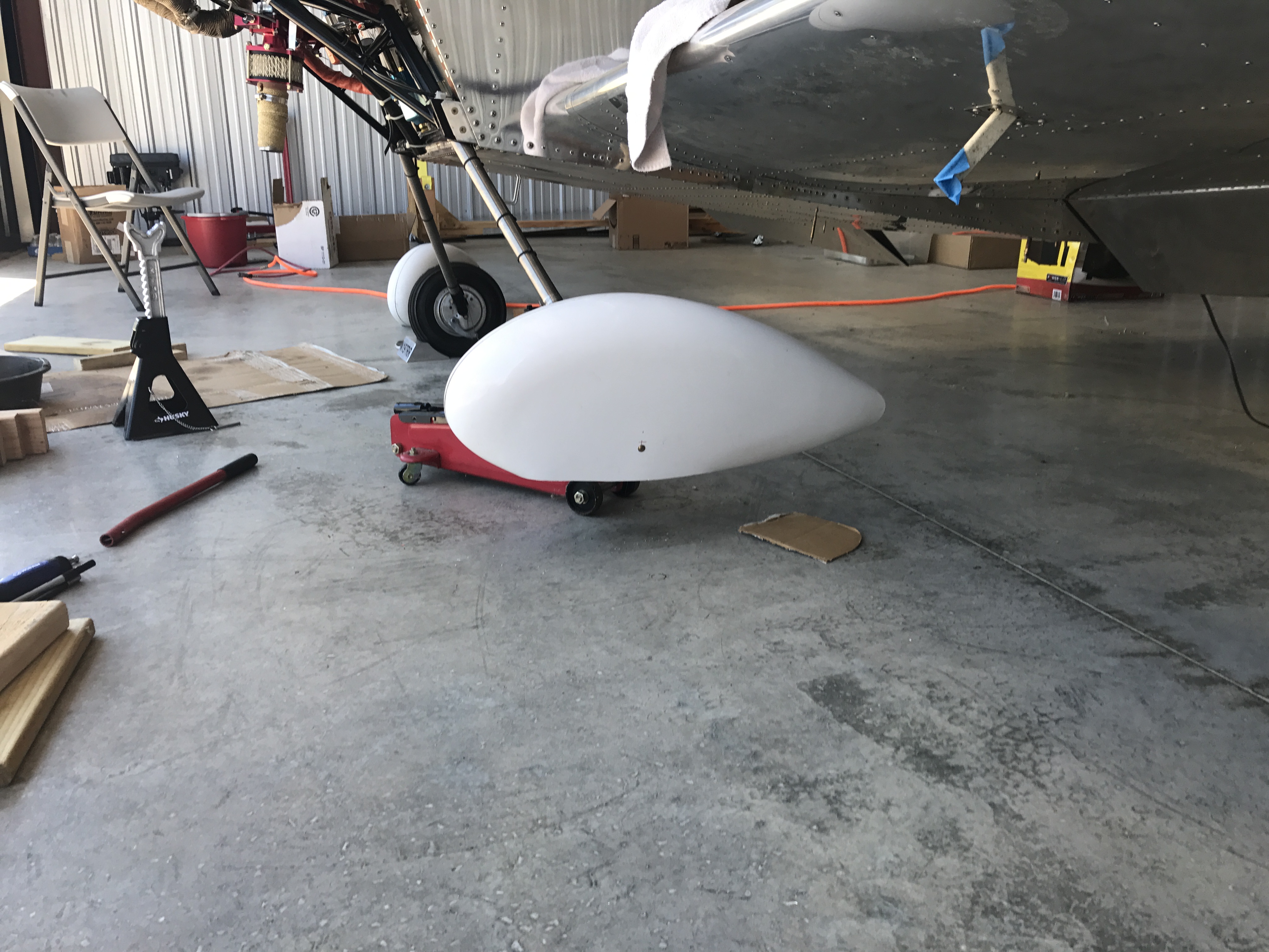
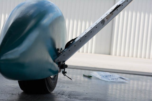
Instead, I went with a method that immediately worked the first time and every time therafter. A hose clamp attached to the titanium gear leg as a jack point.
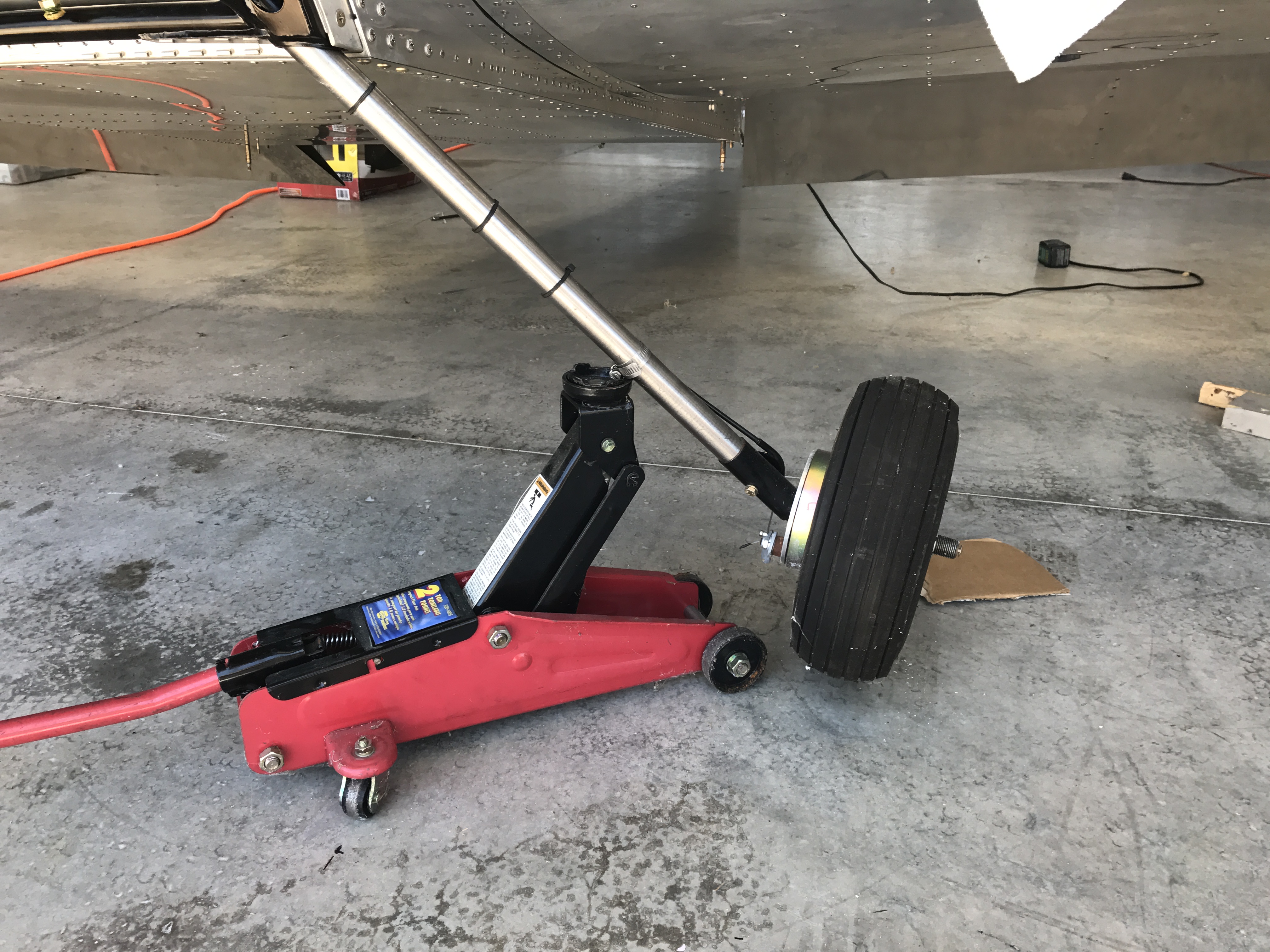
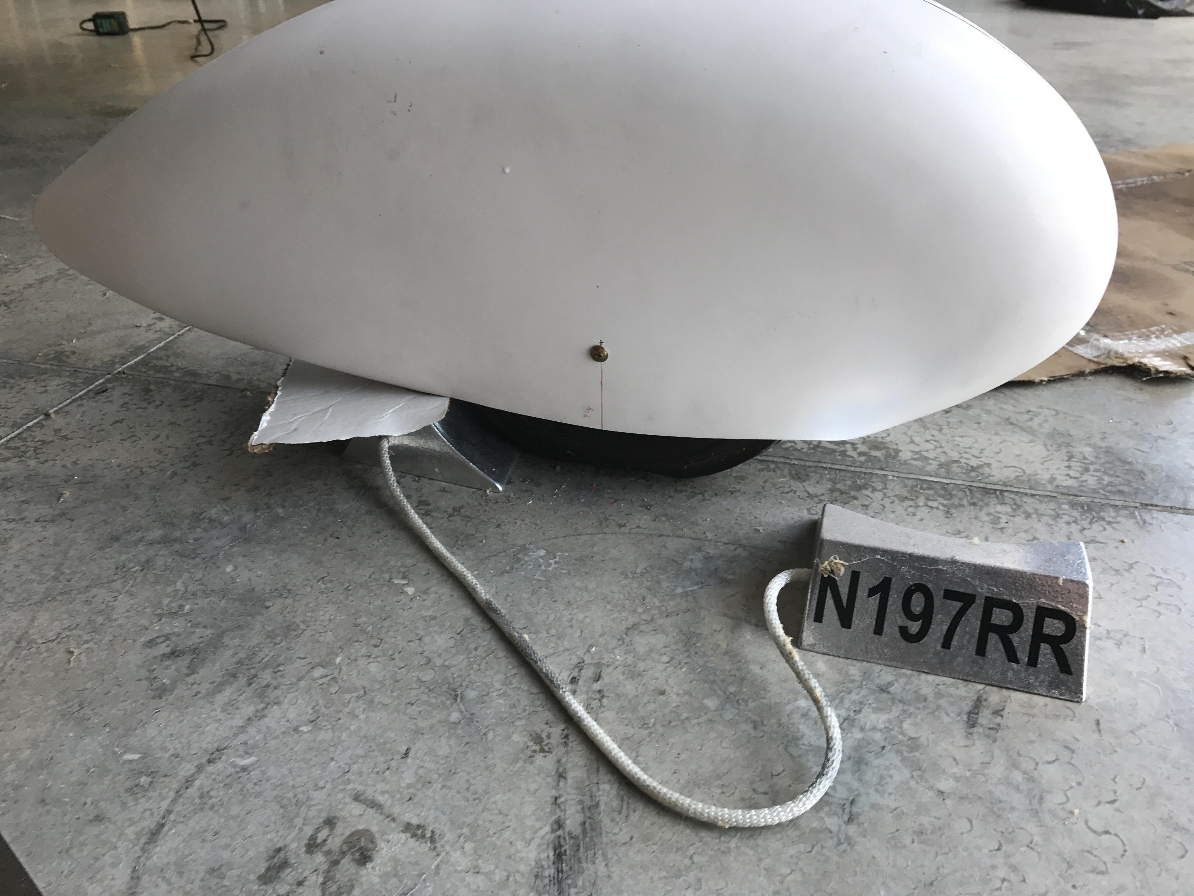
Once I had the wheel removed, I blocked up under the wheel axle as a safeguard.
Additional photo of the right-side being jacked up in a similar manner.
The first time I did this I was extremely careful for fear of scratching the gear legs. The hardness of the titanium however proved to be very resilient, and I was not able to detect any sort of scratching from either the hose clamp or the jack after lifting the leg. I think one improvement to this method would be to add a second hose clamp before jacking, just to reduce the chance of the single hose clamp slipping up the leg.
Wheel Pant Fabrication/Installation:
The fiberglass wheel pants were included in the airframe kit, but required fitment and trimming for installation. The wheel pants shroud the wheels in an aerodynamic shape, providing a drastic reduction in drag.
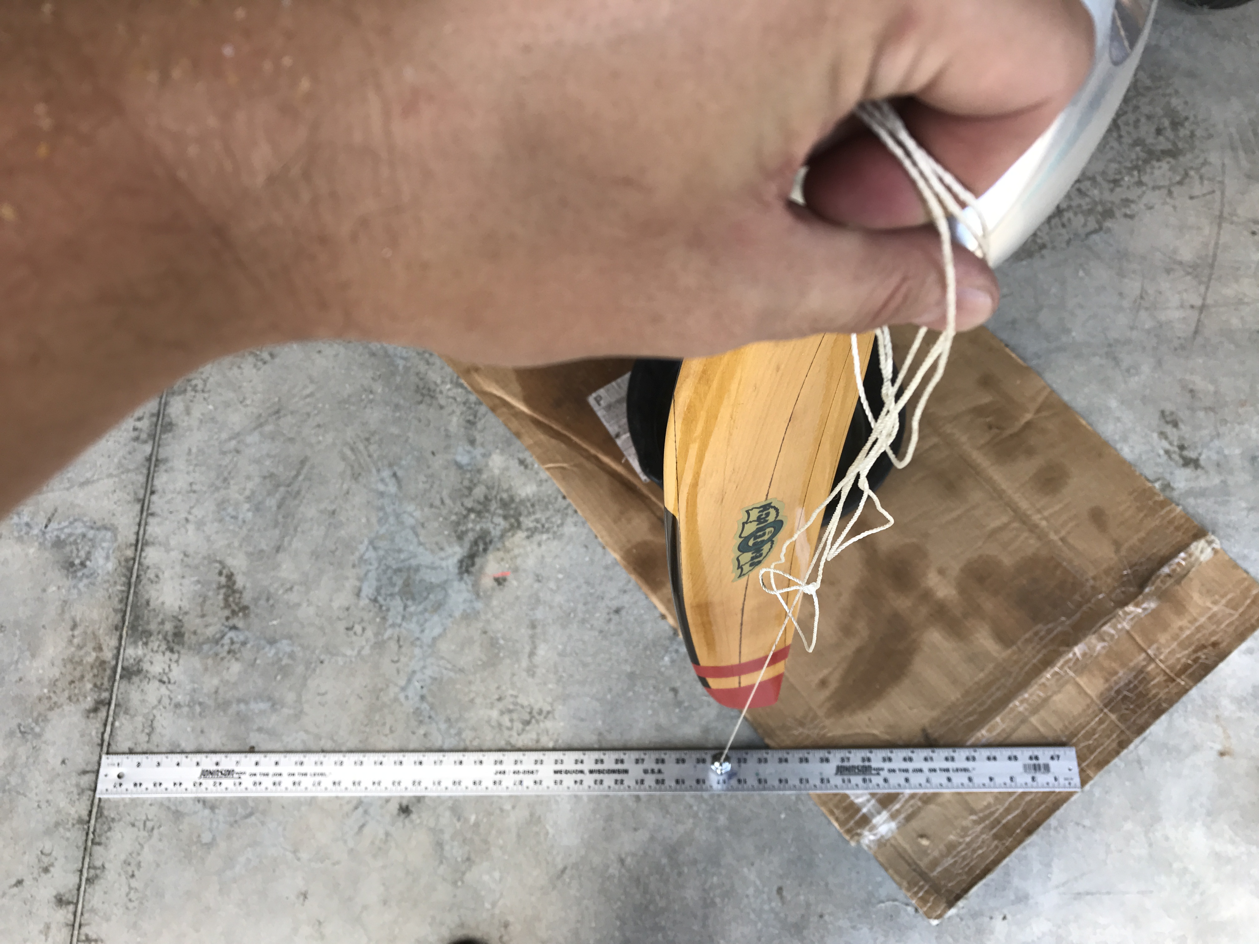
I marked the initial outboard hole and made the inboard cutouts per the plans, then did a test fitment of the wheel pant:
While the outside hole marked the proper location of the wheel pant in relation to the tire, the inside holes would set both the pitch and yaw of the wheel pant in relation to the airframe, so I made some measurements prior to making them.
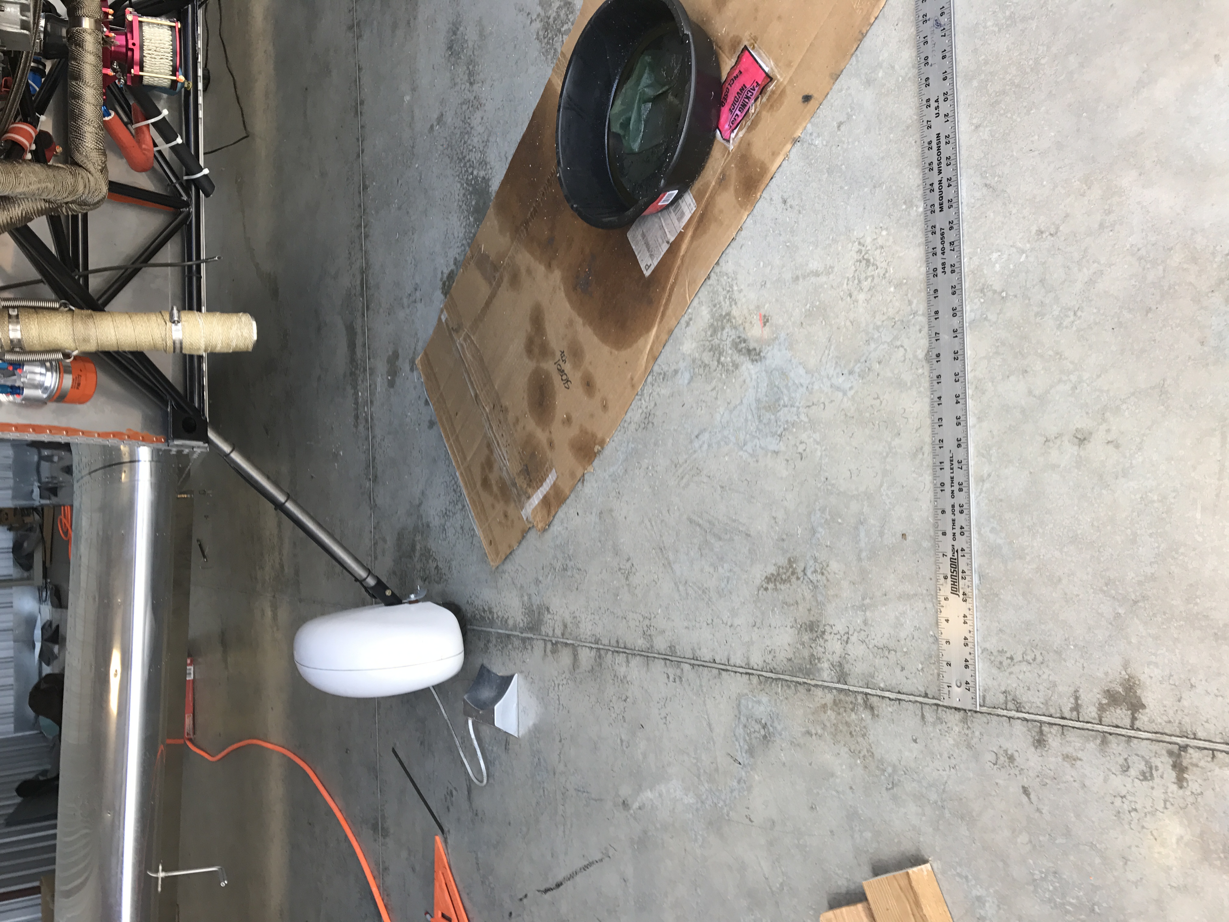
I aligned the aircraft parallel to a line in the concrete, so I could make the wheel pant parallel to the fuselage prior to drilling the inboard holes.
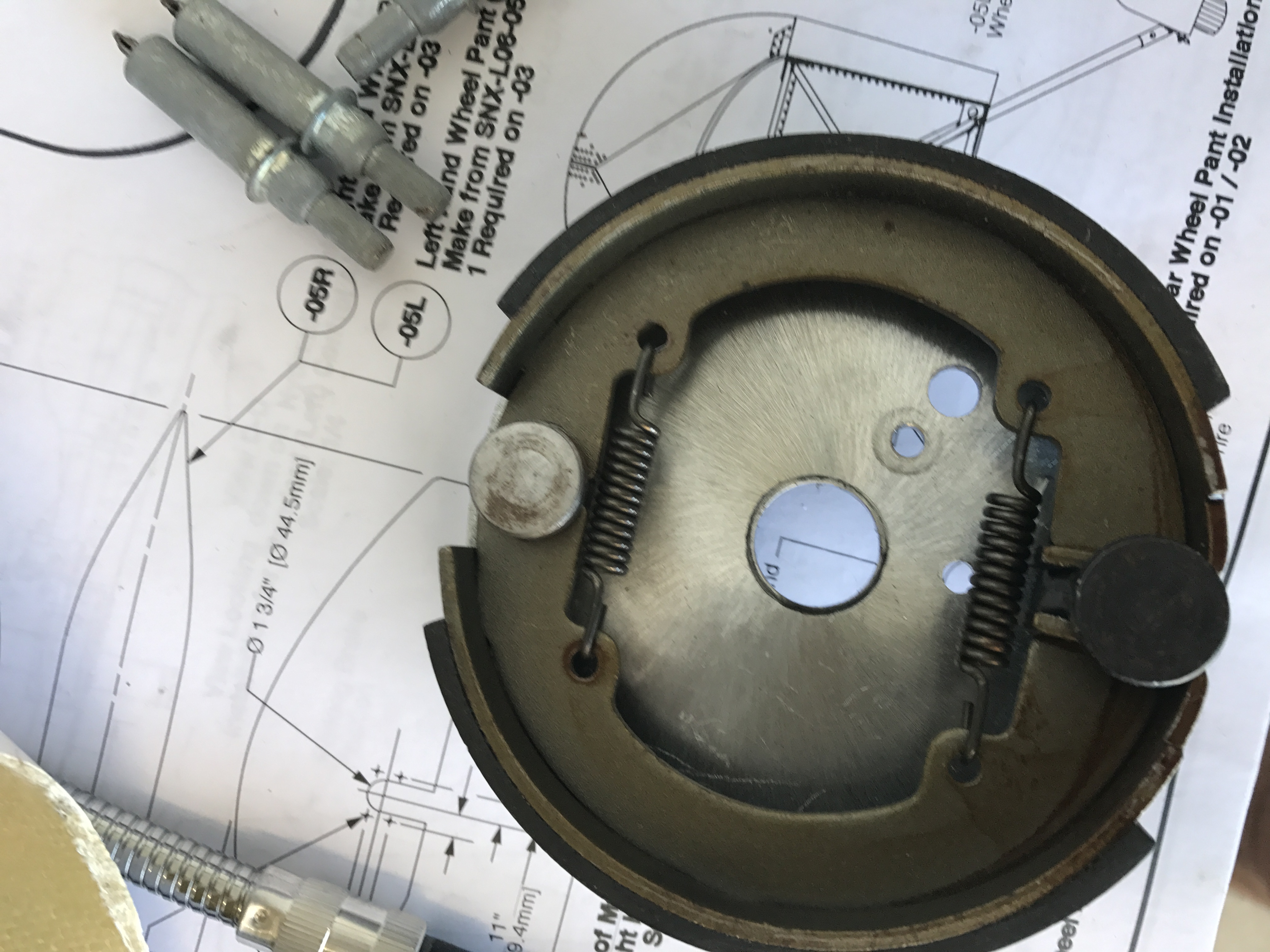
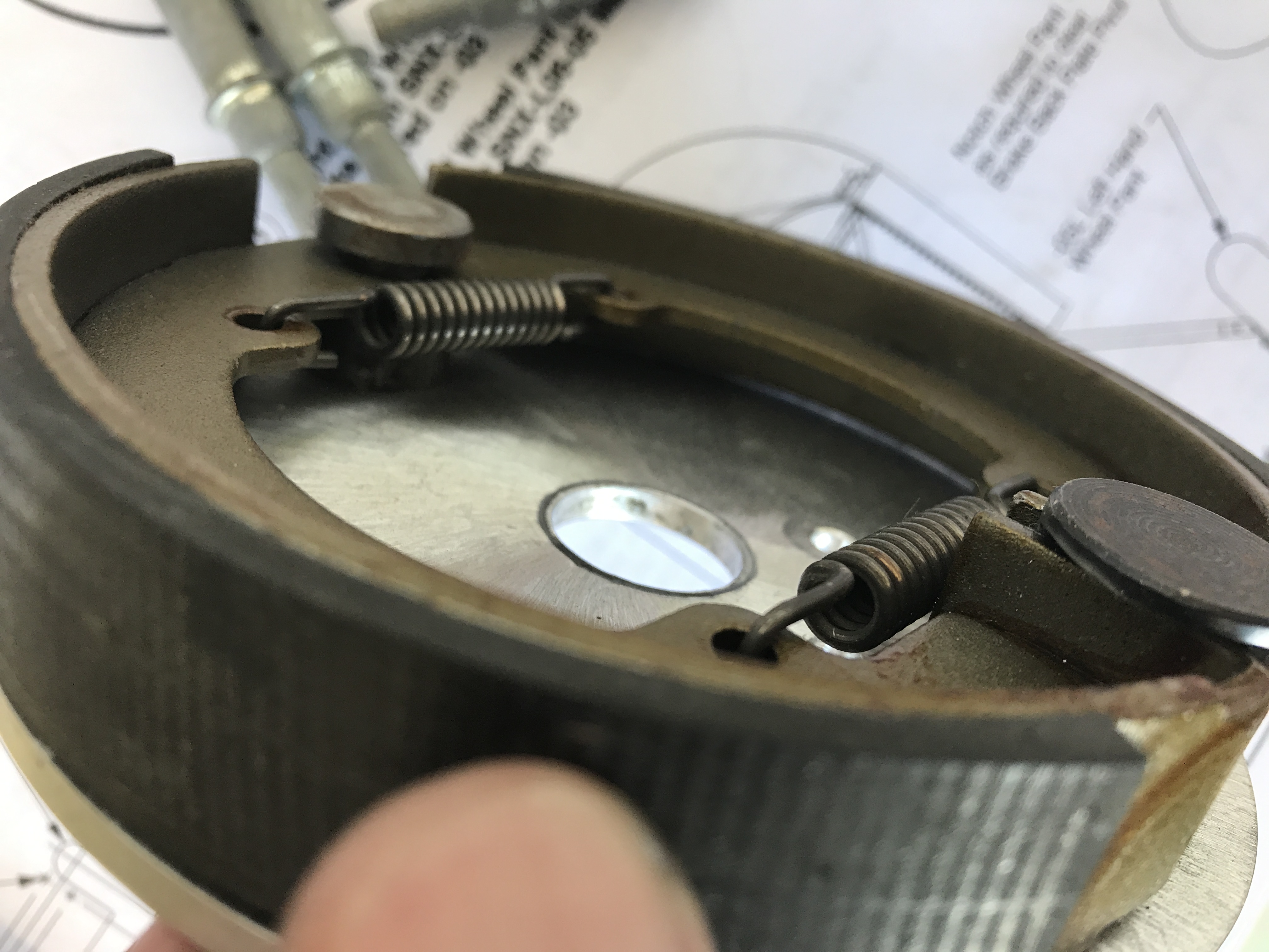
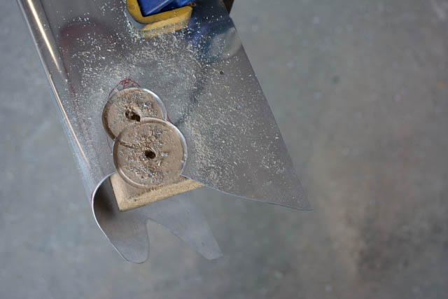
I then marked and removed the wheel brake assembly, which is where the inboard portion of the wheel pant will be attached.
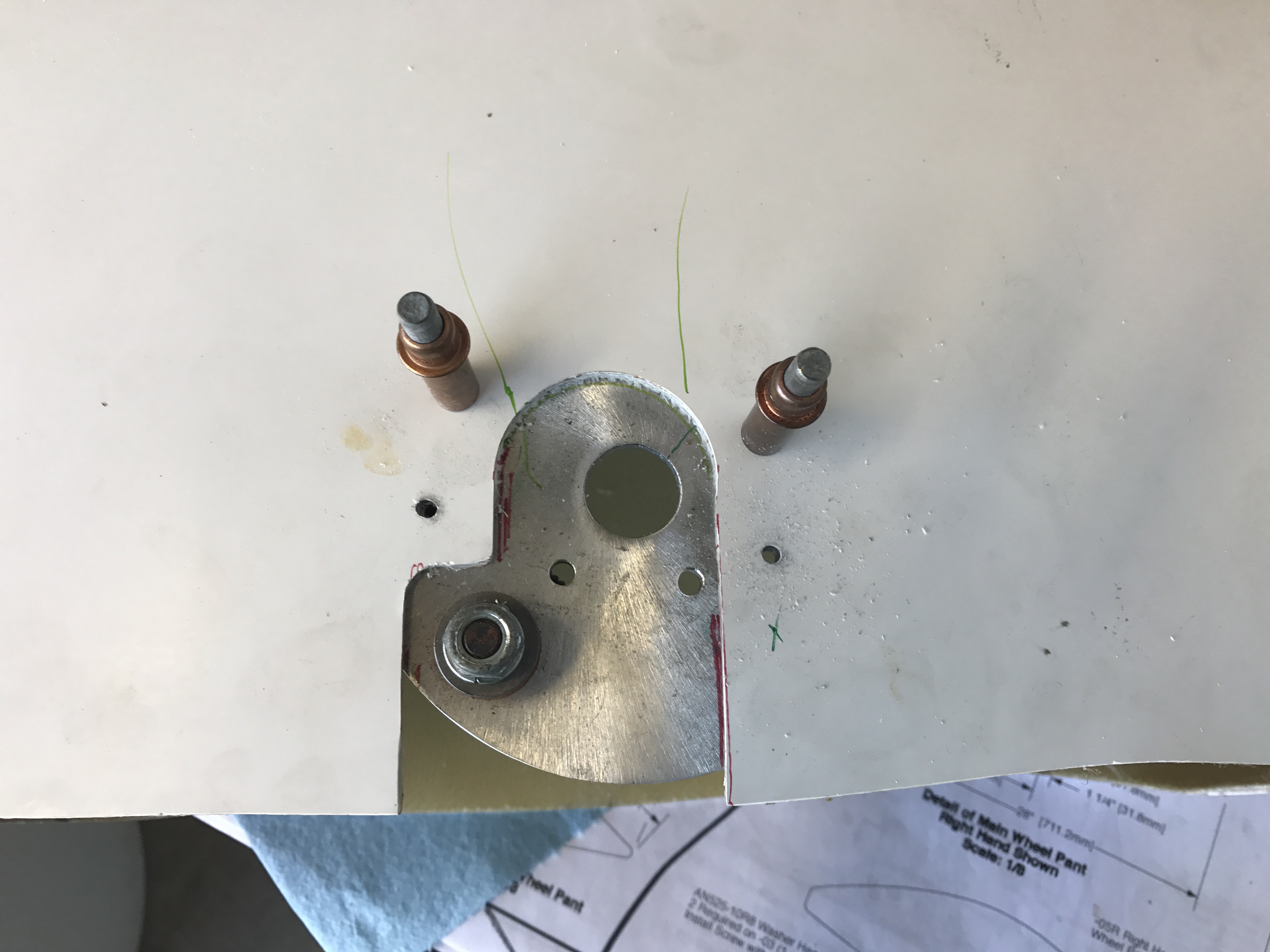
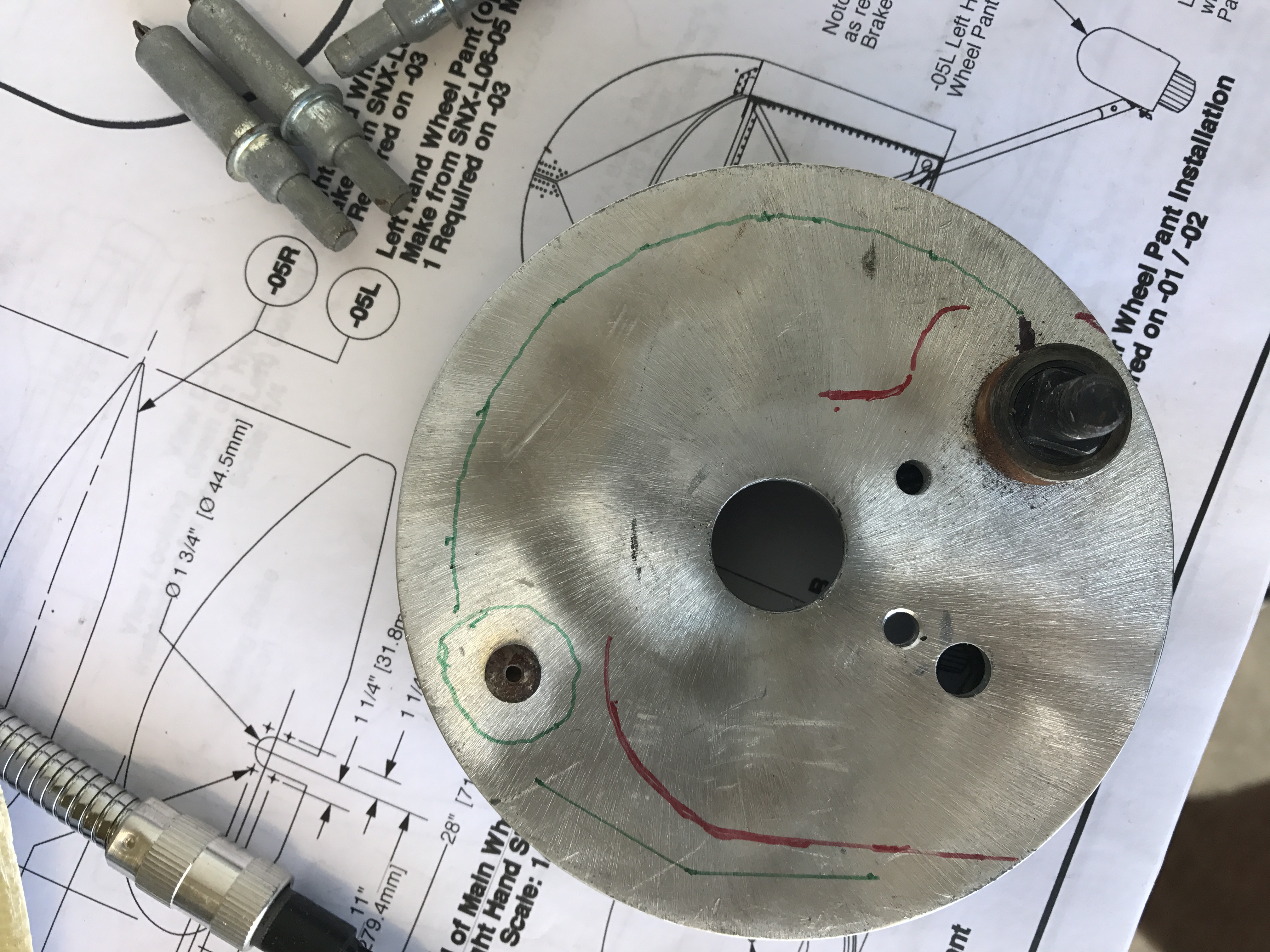
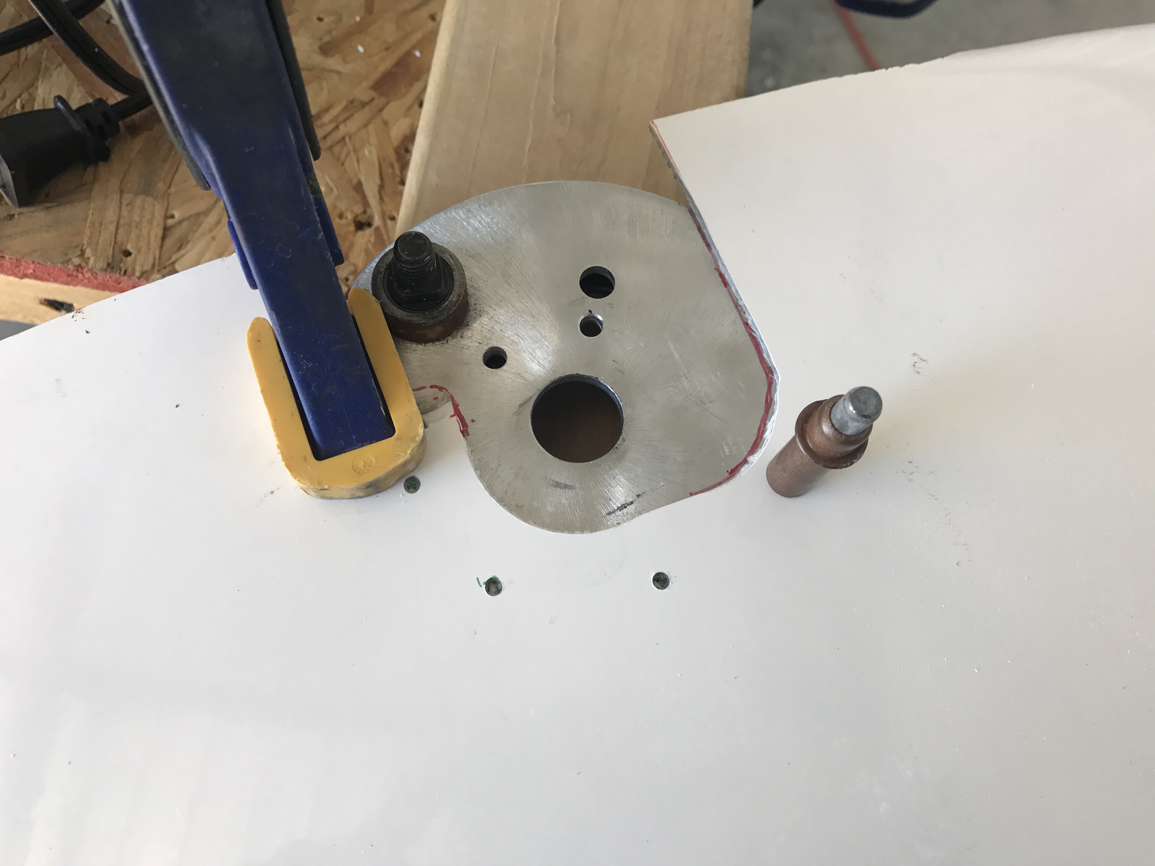
I determined my fastening points, while ensuring the screws would not interfere with the drum brake itself.
Marking, drilling and tapping the holes.
I repeated the process for the opposite side
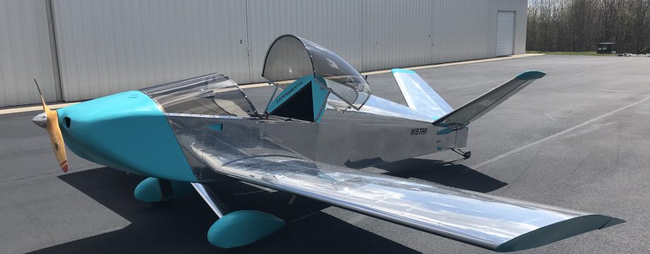
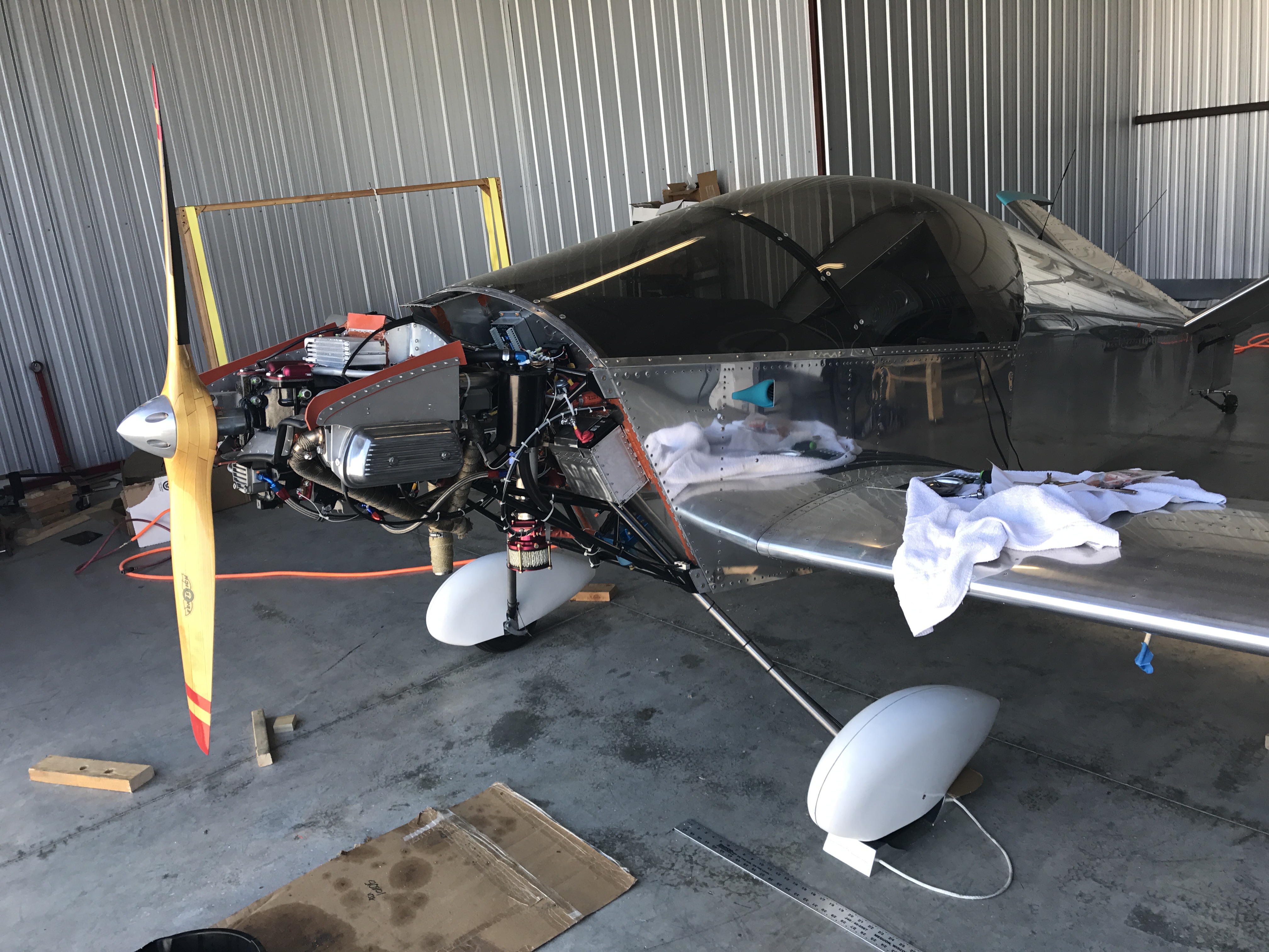
End result, 2 good-fitting wheel pants!
Landing Gear Fairing Fabrication:
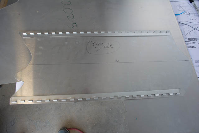
The landing gear fairings cover the titanium gear leg for an aerodynamic reduction in drag. I started the process by making some paper cutouts/mockups of for the fairings, based on the measurements in the plans.
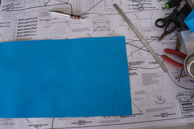
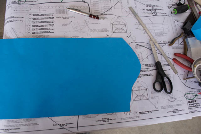
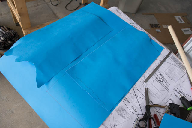
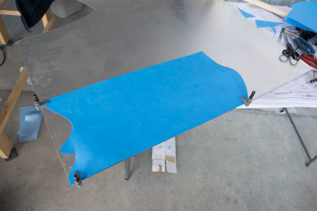
I used these cutouts to go back-and-forth from the gear legs to the drawing table, to come up with a shape that I would cut into the actual aluminum sheet.
I pre-polished the fairings.
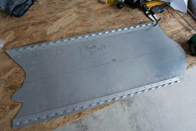
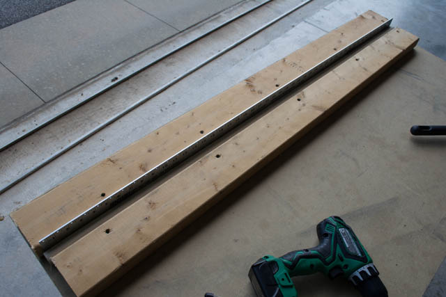
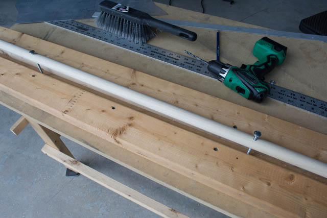
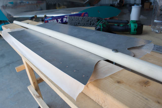
To make the 1″ radius leading-edge bend in the fairing, I made a bending brake from some 2×4’s and a 1″ wooden dowel.
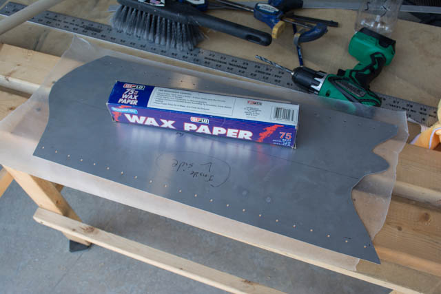
I used some wax paper to provide a lubricating surface between the aluminum and the brake which worked ok.
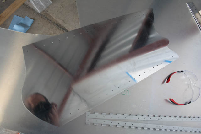
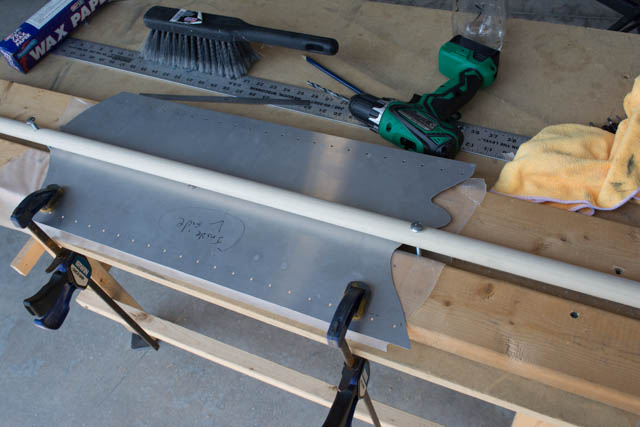
I then made the bend in the fairing. Note: If I did this again, I would double-up and/or provide additional rigidity to the wooden dowel, it bent a lot during this process.
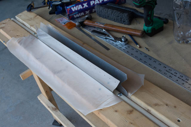
Result after the bend:
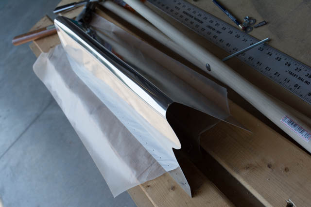
I did not anneal the aluminum, which meant it was still very strong and stiff even after this bend was made. The final fitment of the fairing was a bit of a chore, including the installation of the piano hinges. I ended up re-making one side of the hinges because they didn’t quite align with the original holes I had drilled, prior to riveting.
I also had to drill out quite a bit of additional clearance around the wheel brake, mostly for the brake cable and routing hardware.
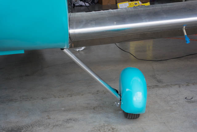
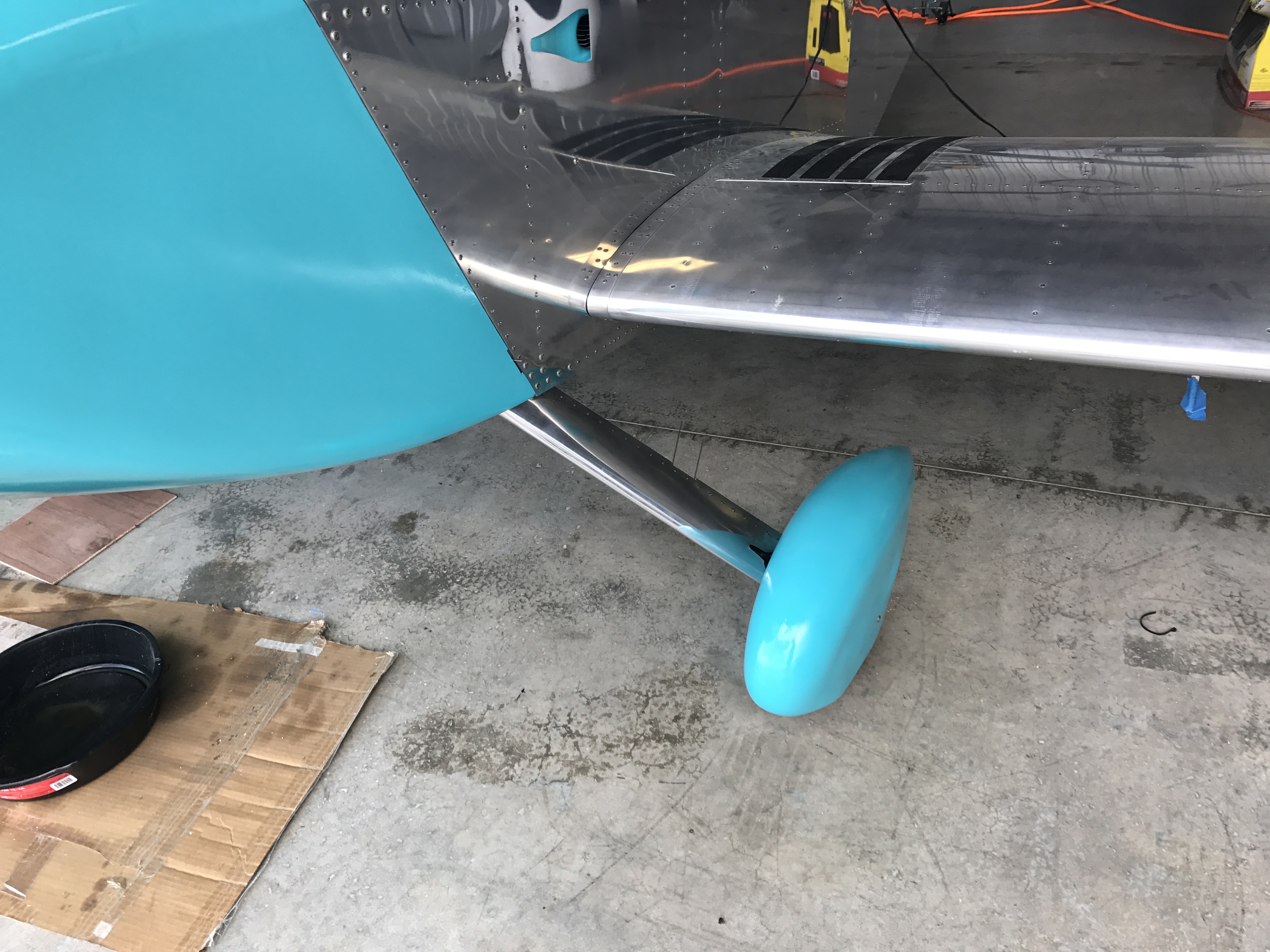
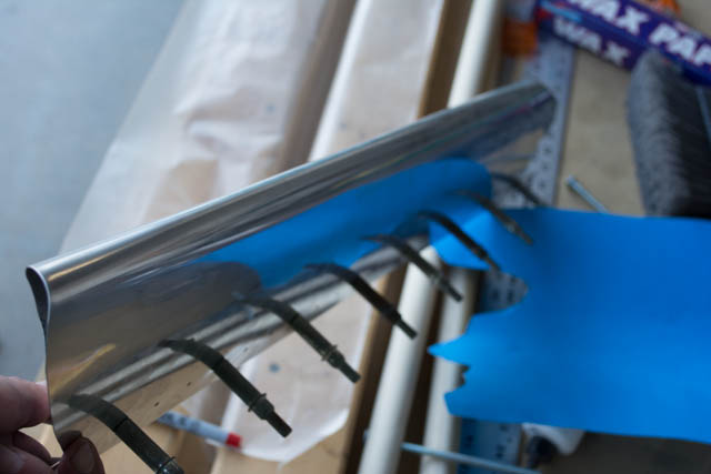
I felt the end result was a good fitment. I did modify from the plans by using 2 separate piano hinge pins that are inserted from the center of the fairing. This makes the fairing able to be installed/removed by a single person.
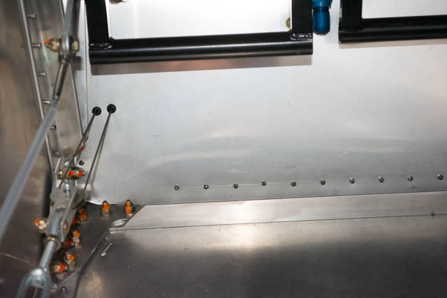
The lower hinge pin pokes through a hole in the wheel pant to maintain its position (short enough to avoid the tire itself.) The upper hinge pin goes through a hole in the floor of the forward fuselage to secure its position.
Both hinge pins will be secured by safety wire at their point of insertion (pins were trimmed after this photo was taken.)
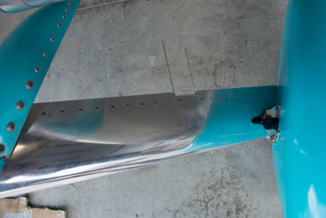
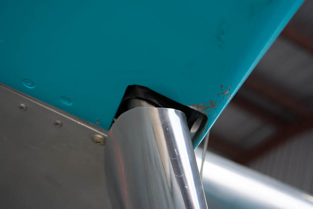
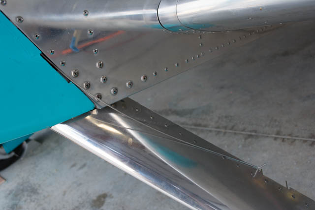
Here are some pics of the interface between the engine cowling/fuselage and gear leg fairings. Of note in the first picture below is the pin used to secure the side of the engine cowling itself… it can be inserted/removed with the fairing in place, meaning that I do not need to remove the fairings in order to remove the engine cowling, which is very convenient.
I do not currently plan to fill this cosmetic gap between the cowling and the fairings, again because it actually makes the cowling easier to install/remove with the wheel pants in place (they are a chore to install/remove due to their stiffness.)