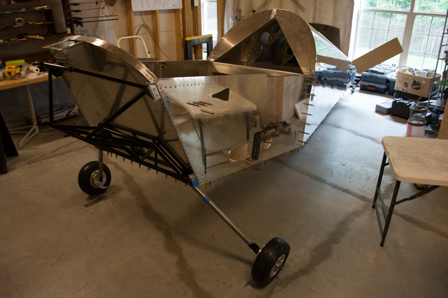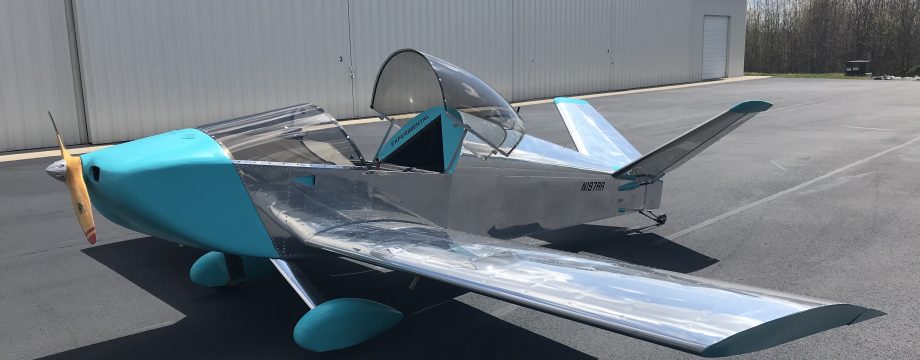
Total Build Time: 681 Hours
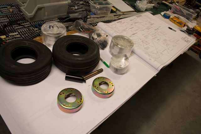
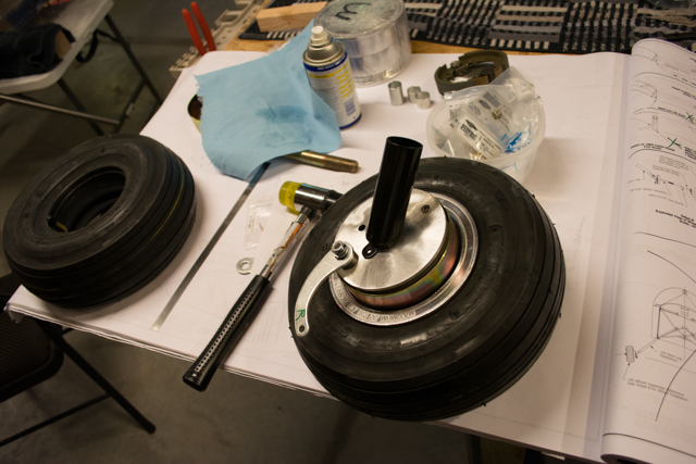
Putting together the wheel assemblies mostly revolved around the brakes and wheel bearings. I don’t have any pictures of the wheel bearings themselves, but I used an automotive synthetic wheel bearing grease to pack them, using the palm of my hand to press the grease through the bearings.
Here is a link to the sonex instruction sheet for this part of the process. http://www.sonexaircraft.com/documents/instruction_sheets/wheel_brake_install.pdf
The drum brakes have a modification suggested by Sonex, referencing this document: http://www.sonexaircraft.com/documents/instruction_sheets/wheel_brake_install.pdf
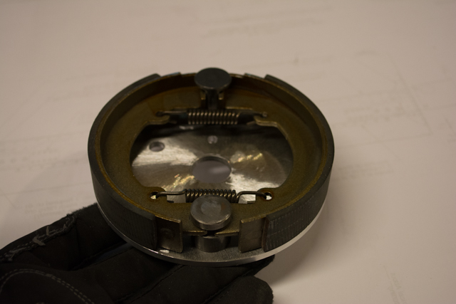
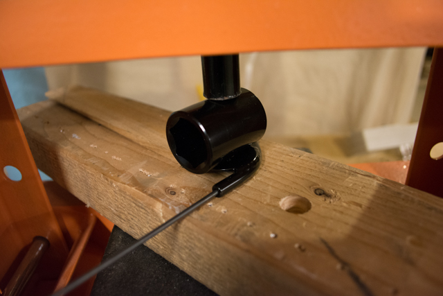
The best way I found to disassemble the brakes (so that I could modify the cam lobes) was to carefully peel them open like a butterfly.
 \
\
At this point I was able to remove each brake pad, pull out the cab lobe and modify it by filing down the corners.

These lobes are what turn when I apply pressure to the brake handle in the cockpit. With the rounded corners, it will allow them to apply pressure more smoothly and gradually to the brake pads, hopefully resulting in smoother brake operation.
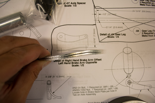
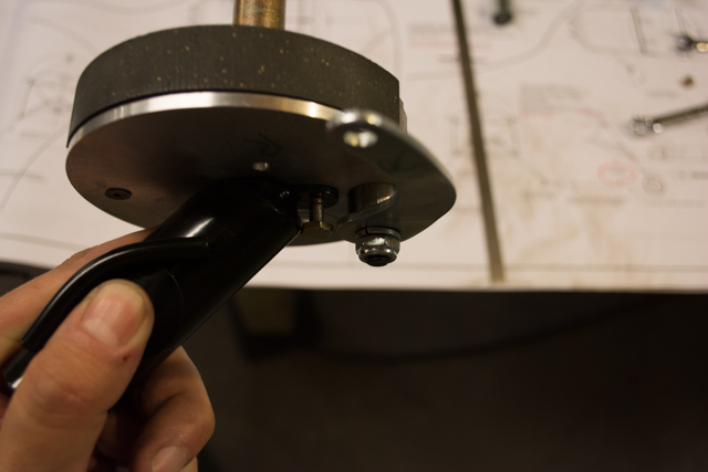
There are some small fittings that must be bent in order to bolt flush to the axle. These fittings contain a tube which will guide the brake cables down the gear leg and to the arm that will turn the brake cam lobes.
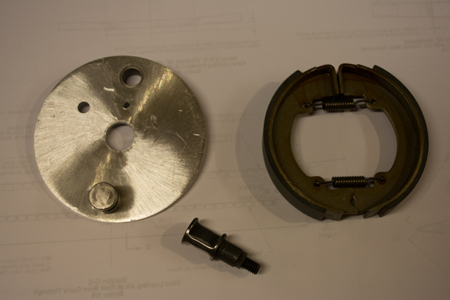
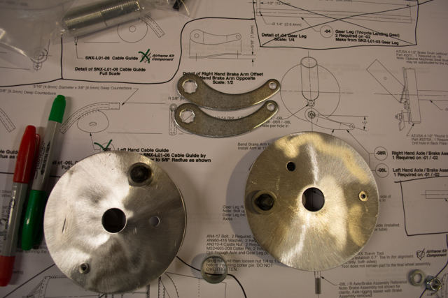
Here are the brakes with the arms that connect to the brake cable. One of the arms will be re-bent in the opposite direction.
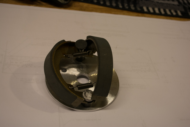
Here is the wheel assembly with the brake inserted.
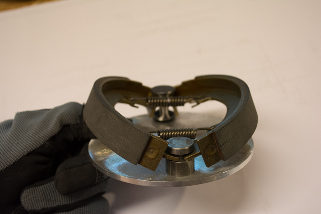
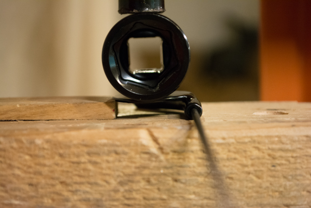
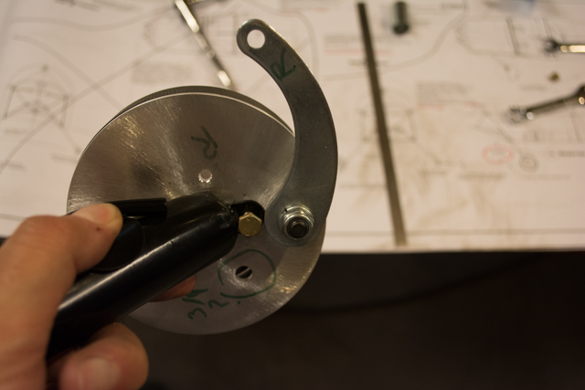
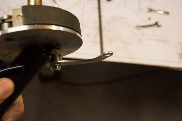
After I had fit everything together per the plans, I noticed that the alignment through which the brake cable will eventually be fitted didn’t look right. If you look at the following pictures, under my thumb is the brake cable guide, and the cable will emerge from the end of that guide and go directly to the tip of the arm that moves the gear. There is quite a sharp angle that the cable will have to make in order to connect in this fashion. I imagined a lot of rubbing and wear on both the cable and the cable guide if things were hooked up in this manner.
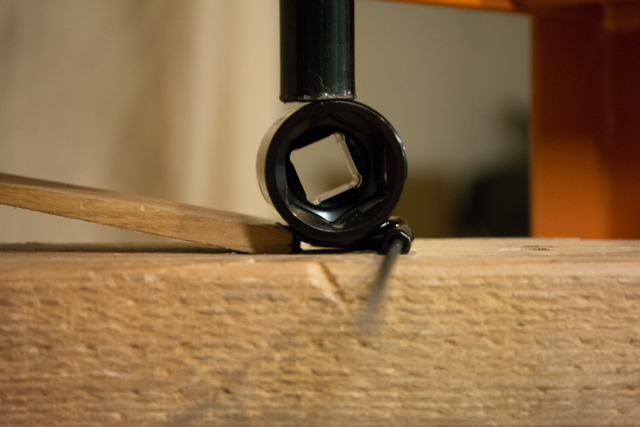
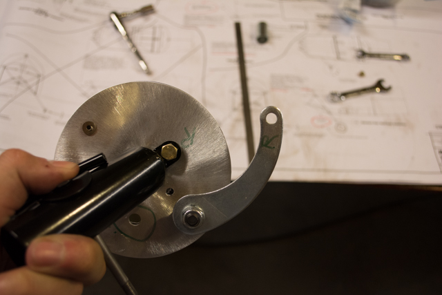
My solution was to simply rotate the drum assembly about 45 degrees relative to the axle, bringing everything into much closer alignment, like so. All this took was to drill a new bolt hole. I can still go back to the old position easily if necessary, but I believe this works out better. Look how much closer the alignment is from the brake cable guide to the tip of the arm.
I don’t have pictures, but I would be sure to tighten the wheel axle nuts tightly before marking your location for the cotter pin in the axle. It takes quite a bit of tightening to fully seat the wheel bearings, and my first cotter pin hole (which I marked when I THOUGHT everything was fully snug) was almost a full 1/2″ too far out on the axle.