
Total Build Time: 307 Hours.
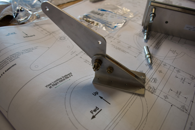
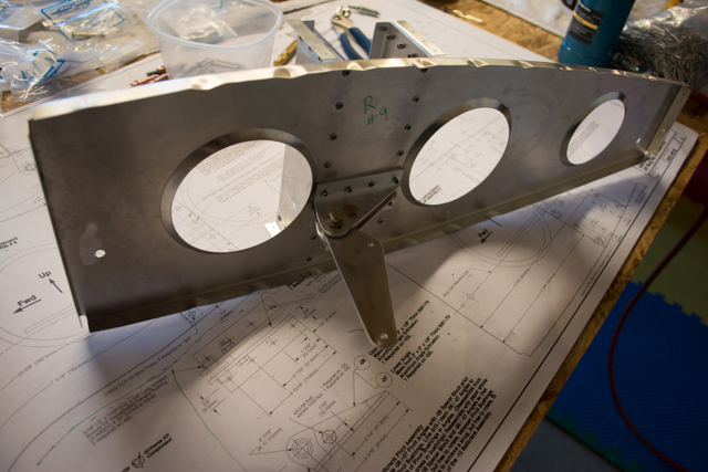
The aileron bell crank assembly marks the first flight control interface I’ve built on the aircraft. As such, I took extra special care in making these parts, 1 per wing.
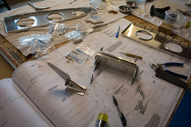
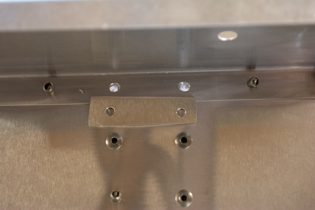
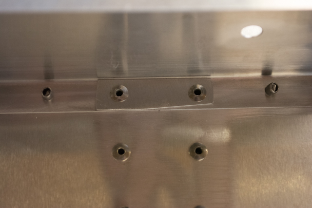
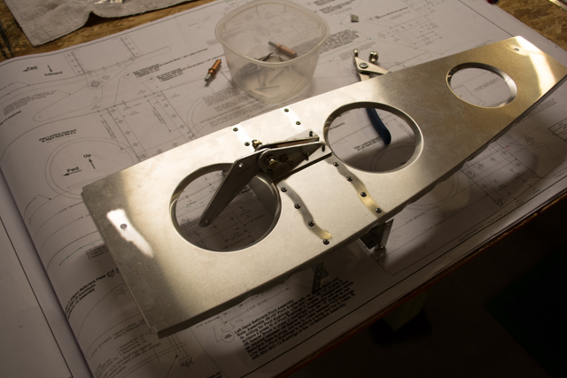
It may be difficult to see in the following picture, but i made the holes in my right side bell-crank angle slightly too narrow which resulted in slightly large holes in the supporting laser-cut channel:
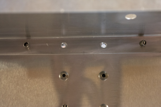
The holes in the fabricated angle and in the rib itself were good. To rectify this I added a shim for the rivets. Tip to future builders: carefully position the supporting channels into position first (via the plans) before drilling pilot holes in the angles. This is an intricate alignment on both sides of the rib.
I spent 11 hours on these 2 bell-cranks, one for either wing. I really wanted to be sure that everything was correct for these two very important flight control interfaces. I lubricated all bushing surfaces liberally with white lithium grease per the plans.
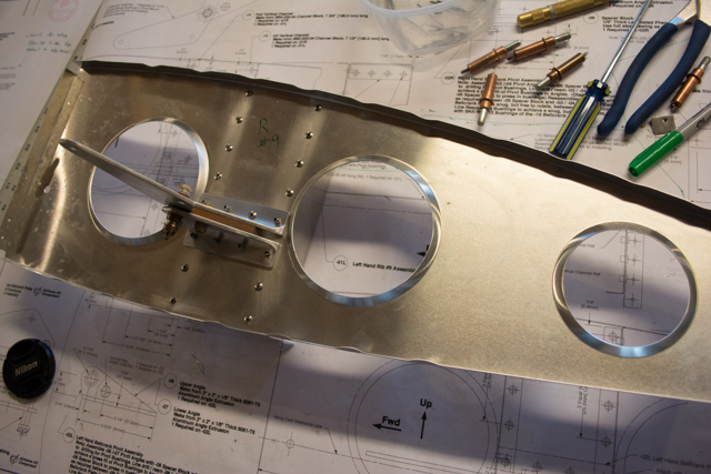
I completed the right side bell-crank first, then the left side. The left side turned out better in terms of smoothness than the right bell-crank. I then went back and spent several more hours on the right side, and ended up replacing both steel bushings, bolt, and nut before settling on a smoothly operating bell-crank assembly.
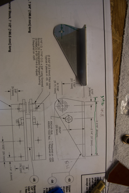
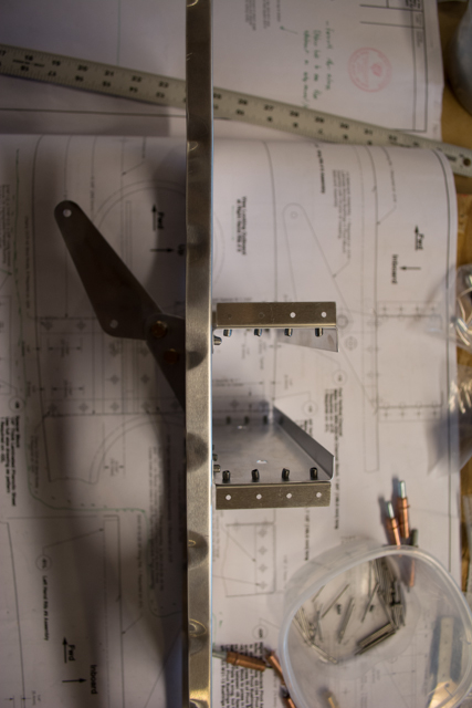
To match drill the holes in the angles for the 7/16″ brass bushings, I drilled through both (assembled together with phenolic spacer) using a 3/8″ bit, then used a step drill bit on each side separately to increase to 7/16″. This resulted in a nice press-fit hole on both angles that aligned very well.
The 3/16″ (inner) steel bushings required reaming to 3/16″ to snugly fit the an3 bolts. They were far too tight on the bolts otherwise. Likewise I had to slightly ream the brass bushings for the steel bushings to rotate freely within.