
Total Build Time: 910 Hours.
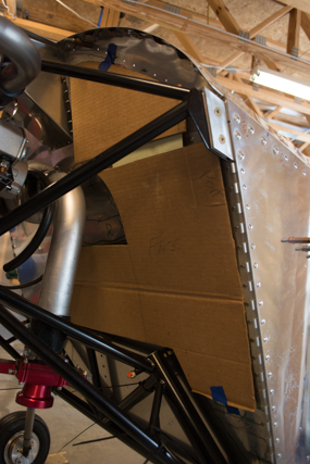
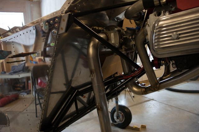
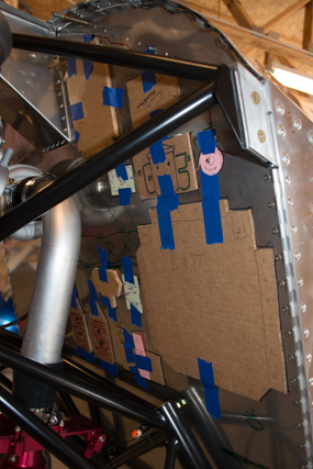
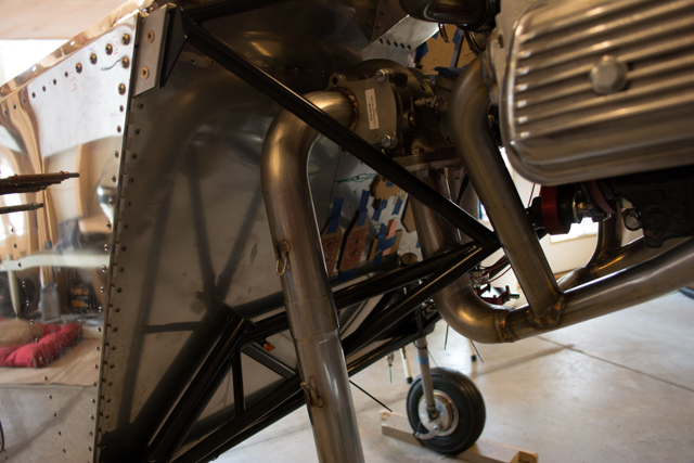
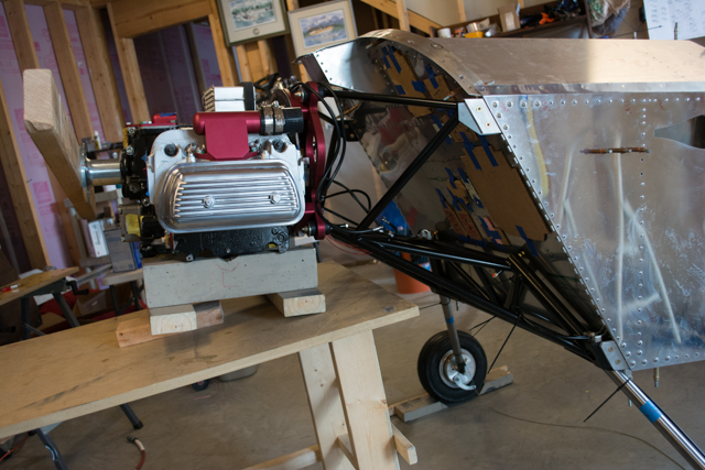
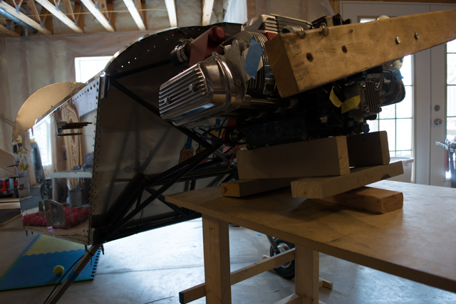
Once I had the engine, exhaust and intake mocked into place I could plan the firewall layout. First step was to identify the usable area on the firewall. I then (with help from Bill) made some cardboard cutouts to assist with planning the layout.
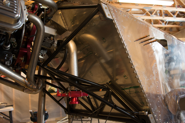
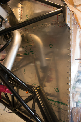
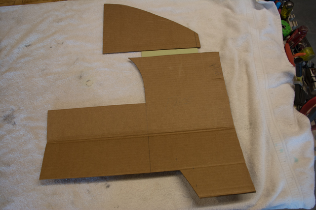
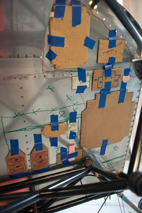
The cutout below represents my usable space on the firewall, including the upper firewall ahead of the fuel tank. I discovered there is enough of a gap between the upper firewall and fuel tank to mount nutplates, so I can use that space to attach components on the engine side of the firewall.
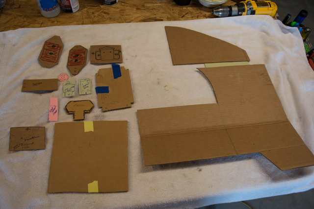
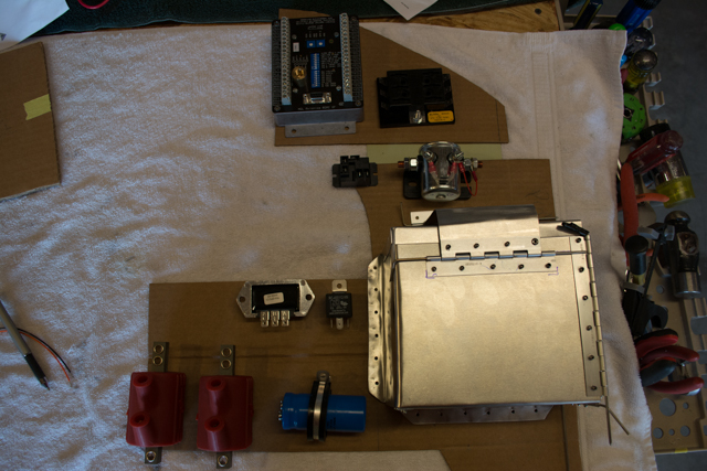
We then made cardboard cutouts representing all of the components that must go on the firewall.
From top to bottom and left to right, the components in the picture below are:
Top: Master contactor (for battery master switch)
Row 2: Ignition coils x2, alternator overvoltage relay, secondary ignition relay, MGL RDAC (remote data aquisition computer, which gather data from all engine probes and sends them to my iEfis display in the cockpit.)
Row 3: Capacitor for alternator power conditioning, voltage regulator.
Bottom row: Fuse block for Main Bus. Battery box.
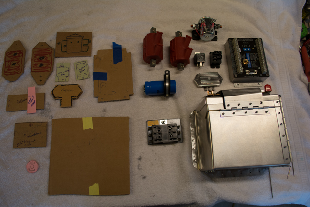
Obviously it’s going to be tight to fit everything!
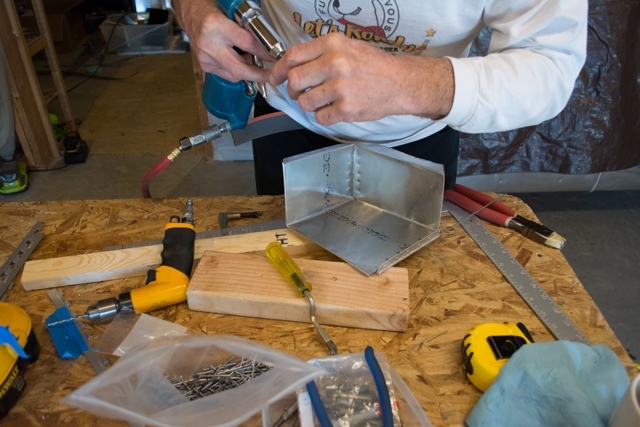
The largest component that needed to go on the firewall was the battery.. there was really only 1 spot it could go, so everything else would need to be planned around its location. Bill made this his pet project while he was in town and did a great job making a custom battery box for me. The dimensions are the same as provided in the Sonex plans for an Odyssey PC625 battery, with the addition of piano hinges to allow for removal from the side (rather than from the top.) The frame of the engine mount prevents removing the battery from the top, so this was the only way I could make it work.
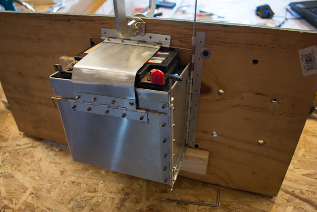
Here are some pics of the battery box coming together, including mockups to ensure proper operation and orientation.
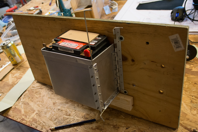
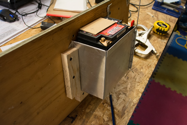
The design allows the pins on the right side of this photo to be removed so that the whole right panel comes off, and the battery easily slides out the side.
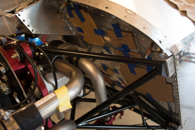
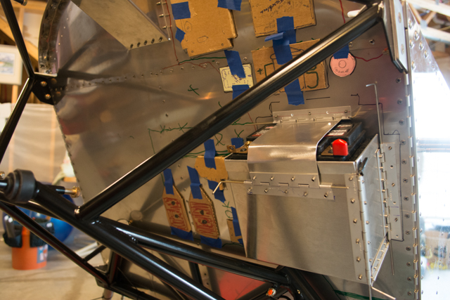
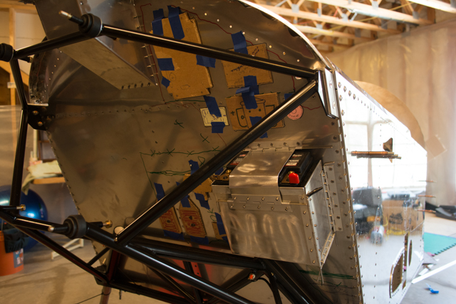
After trying many different arrangements, this is my (mostly-) final layout for the firewall.
I test fit these components multiple times for clearance, then marked up the firewall itself so I can start installing components once the engine is removed.

I then pulled the engine back off, and removed the windshield, glareshield and fuel tank to allow full access to both sides of the firewall.
Here is the marked-up firewall with the engine removed.
Battery box was installed first.
At this point I received some parts I had been waiting for to complete the canopy, and switched gears back to canopy work. I’ll make another future post once I come back to finishing up the firewall prep.
Hi Ryan,
This is AL Roberts. Sorry if this question is off the subject of this post, which I appreciate the way you have went to so much work planning out your firewall accessory locations. I will more than likely do a battery box patterned after yours, but my question is regarding the landing gear. How stiff is it? Does those steel rods have enough flex to withstand “Pranging it In”? Which could happen to any of us, especially me.
Thanks for your interest in other builders.
AL Roberts
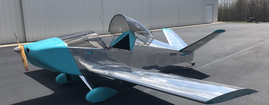
The gear legs are actually titanium, and my understanding is they have a good bit of “spring” effect. I haven’t flown on them yet though, so can’t give you much more than that.
Thanks for this Ryan. It seems as though I may have forgotten one or two things that need to go on the firewall before I put the engine on!
Please keep us all informed about the early engine runs.
Best wishes
Tim Mobbs
Sonex #1555 Aerovee #0672
Bungay Suffolk England