
Total build time: 381 hours.
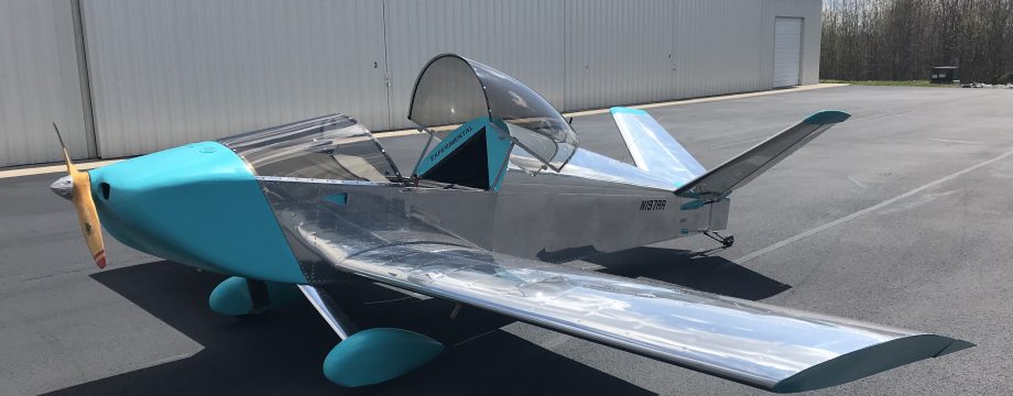
All of the left wing is now deburred and I’m ready to install my first significant customization to my plane. I decided to install a “Lift Reserve Indicator (LRI)” made by Kelly at Value Engineering. An LRI indicator is basically a poor pilot’s angle of attack indicator, and/or stall warning gauge. A probe with 2 holes attached to a differential pressure gauge that measures the difference in airflow between the 2 holes, giving you a sort of angle of attack indication regardless of aircraft weight or orientation.
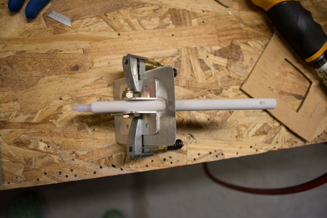
The white probe itself is actually made on a 3D printer. The plastic has the feel more of ceramic, and it has a weighty feel to it. I’m satisfied it will be up to the task.
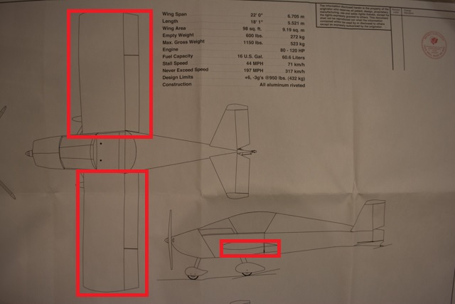
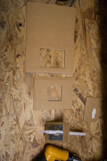
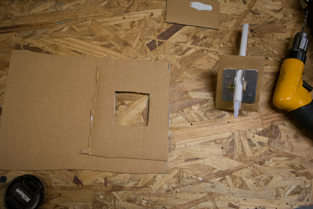
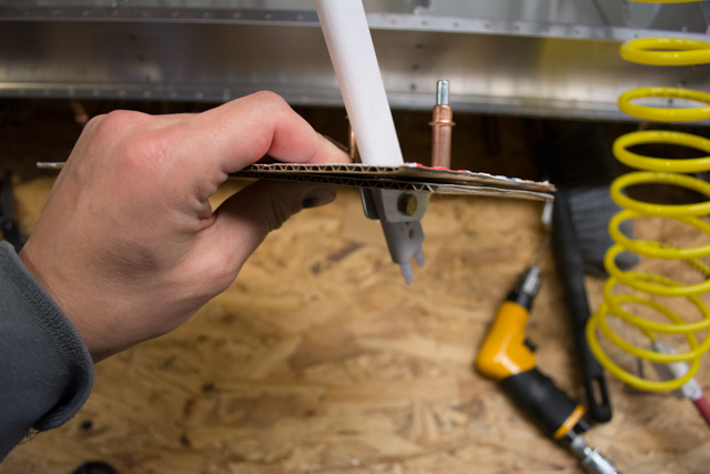
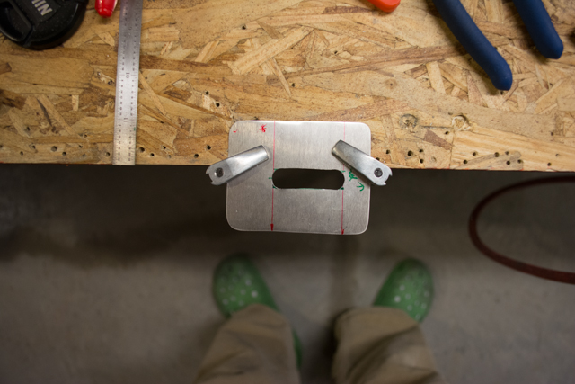
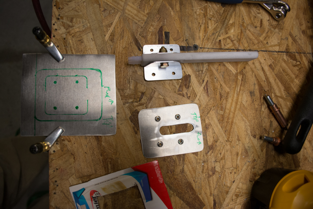
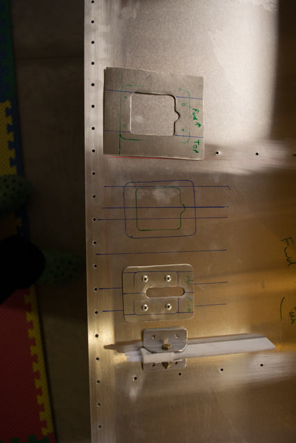
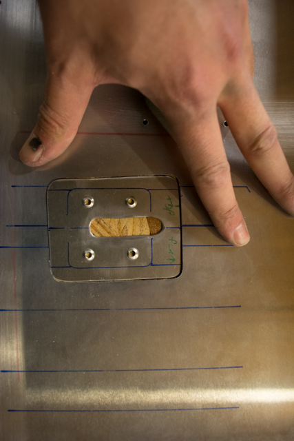
I decided to flush mount my probe on the left wing, in the same location that the pitot/static probes reside on the right wing. A proper flush mount, as it turns out, takes a lot of work. I started by using cardboard cutouts. In the first picture below, the top piece of cardboard represents the wing skin, the middle represents the backing plate, and the bottom is the mounting plate. This should result in a clean installation where only the tip of the probe and the screws holding it will protrude into the airflow.

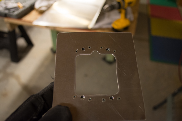
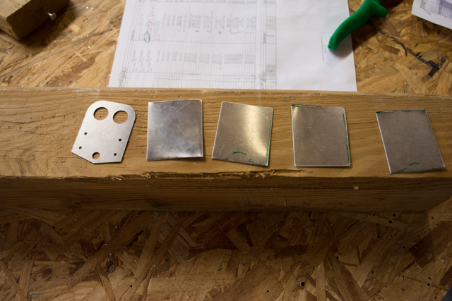
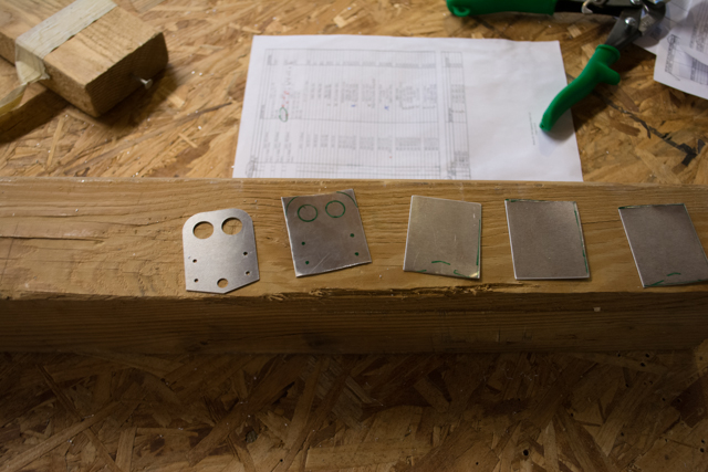
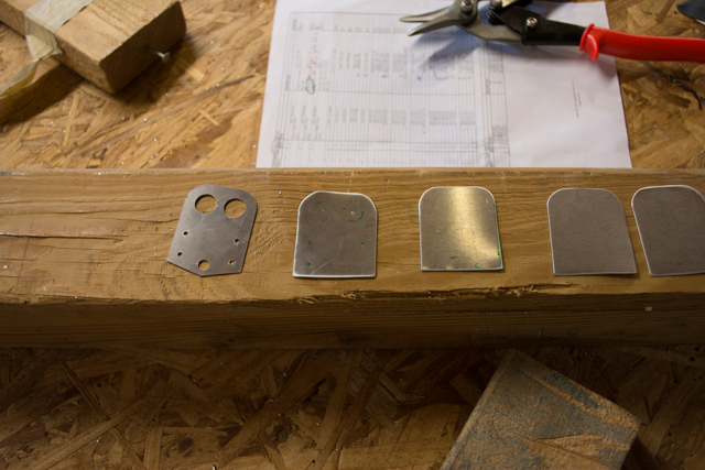
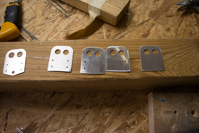
Satisfied with my plan, I began fabricating aluminum parts.
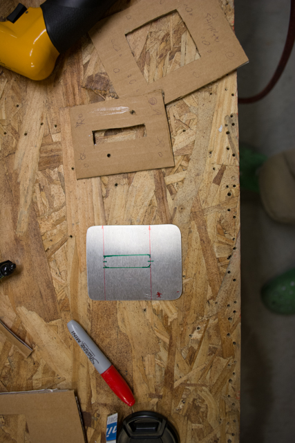
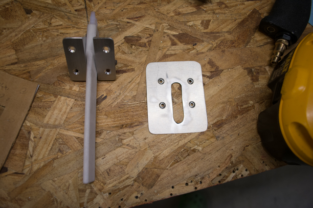
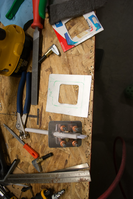
That was the mounting plate. I dimpled and countersunk for flush rivets, and then created the backing plate.
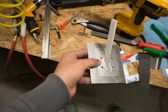
Then came the nerve-wracking job of cutting a hole in the leading edge skin that I just spent a lot of time prepping for assembly. I double-checked all clearances to internal wing components, drew lines to indicate proper alignment with the airflow, and got to work. I used a dremel cutoff wheel and a lot of filing to finish the hole.
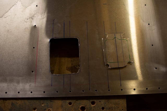
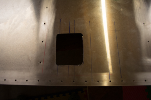
Another way to do this would have been to start with the hole in the skin and make my mounting plate using the hole as a guide. That probably would have resulted in straighter lines. The reason the hole is a little out of alignment is because the probe ended up slightly out of alignment on the mounting plate itself (and the plate is not perfectly square.) The end result is that the probe is properly aligned with the airflow with the hole cutout in this manner.
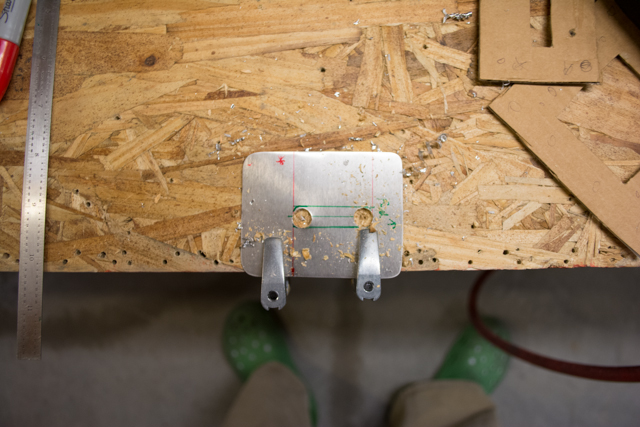
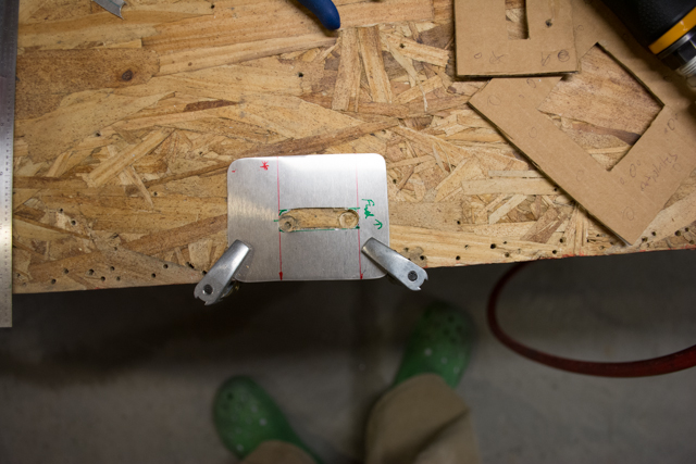
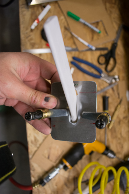
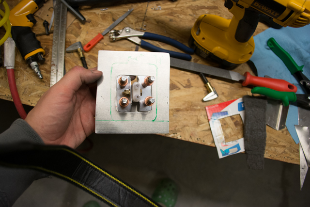
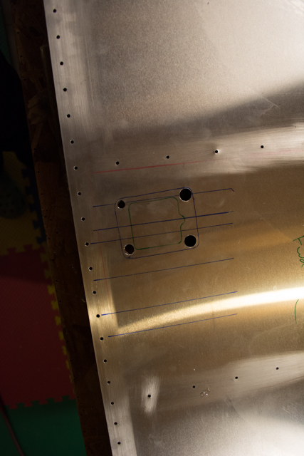
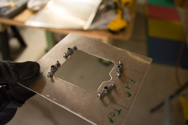
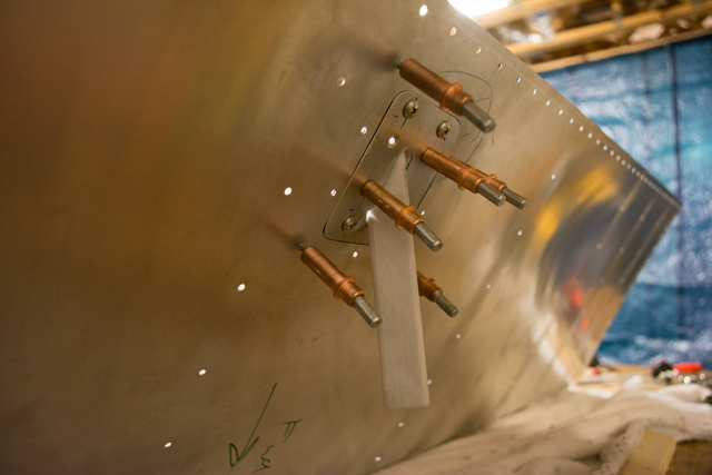
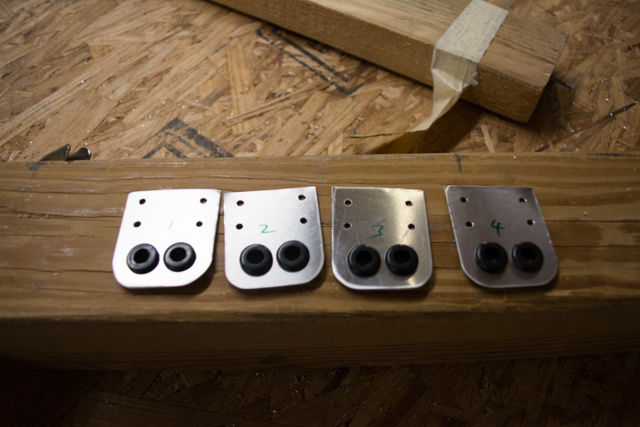
I installed nut-plates on the backing plate so I would have secure and easily removable access to the entire probe. It will have to be calibrated so I need easy access to the nut that holds the probe in position.
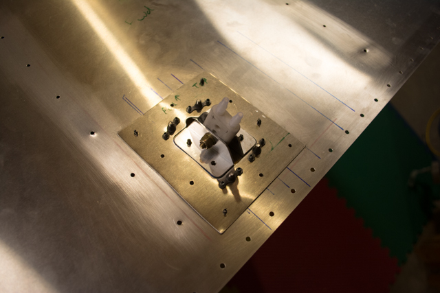
All of the necessary rivet holes are then drilled with everything in alignment. Other than some dimpling and riveting that comes after polishing, the installation is ready.
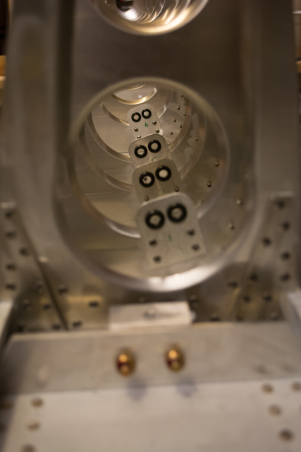
I also need to route the tubing through the wing from the probe to the instrument. To do so I just copied the method the plans show with the pitot/static lines. I fabricated duplicates of the line holders and installed them on forward ribs 1-4. The extra hole isn’t necessary as it is only used as a locator with the tooling holes in the ribs.
At this point everything for my left wing is deburred and ready to install. I will polish the outsides of all 3 wing skins prior to dimpling and riveting.
Ryan,
Good pictures and explanations which will come in handy soon, as I just started on my wings and purchased the same LRI a few weeks ago.
Darick
Sonex #1646
Thanks Darick! If I made this mount again (and I may yet change it) I would make it out of at least 0.32″ thick sheet. It wouldn’t be as flush with the skin, but it would have less flex to it. I’ll find out if it matters once I’ve got the thing in the air!
Are the inserts in your line holders rubber grommets or the hard plastic snap in type, suggested on the Sonex hardware list?
Just rubber grommets from Radio Shack. They needed to be a different size than the hardware list grommets to fit the tubing provided with the LRI. I suppose you could just duplicate the tubing and grommets for the pitot installation, but the barbs on the 3D printed LRI are a different size and you’d have to use an adapter to fit the size of the pitot tubing.
Did you make the probe or buy it? If you made it, can you share the CAD drawings? Thanks!
I bought the probe. There’s a link to Kelly Engineering at the beginning of this blog post.